Home
LEGRAND
Intercom System
D45 SYSTEM
LEGRAND D45 SYSTEM User Manual
5
of 1
of 1 rating
254 pages
Give review
Manual
Specs
To Next Page
To Next Page
To Previous Page
To Previous Page
Loading...
entrance panel video
mixer connection
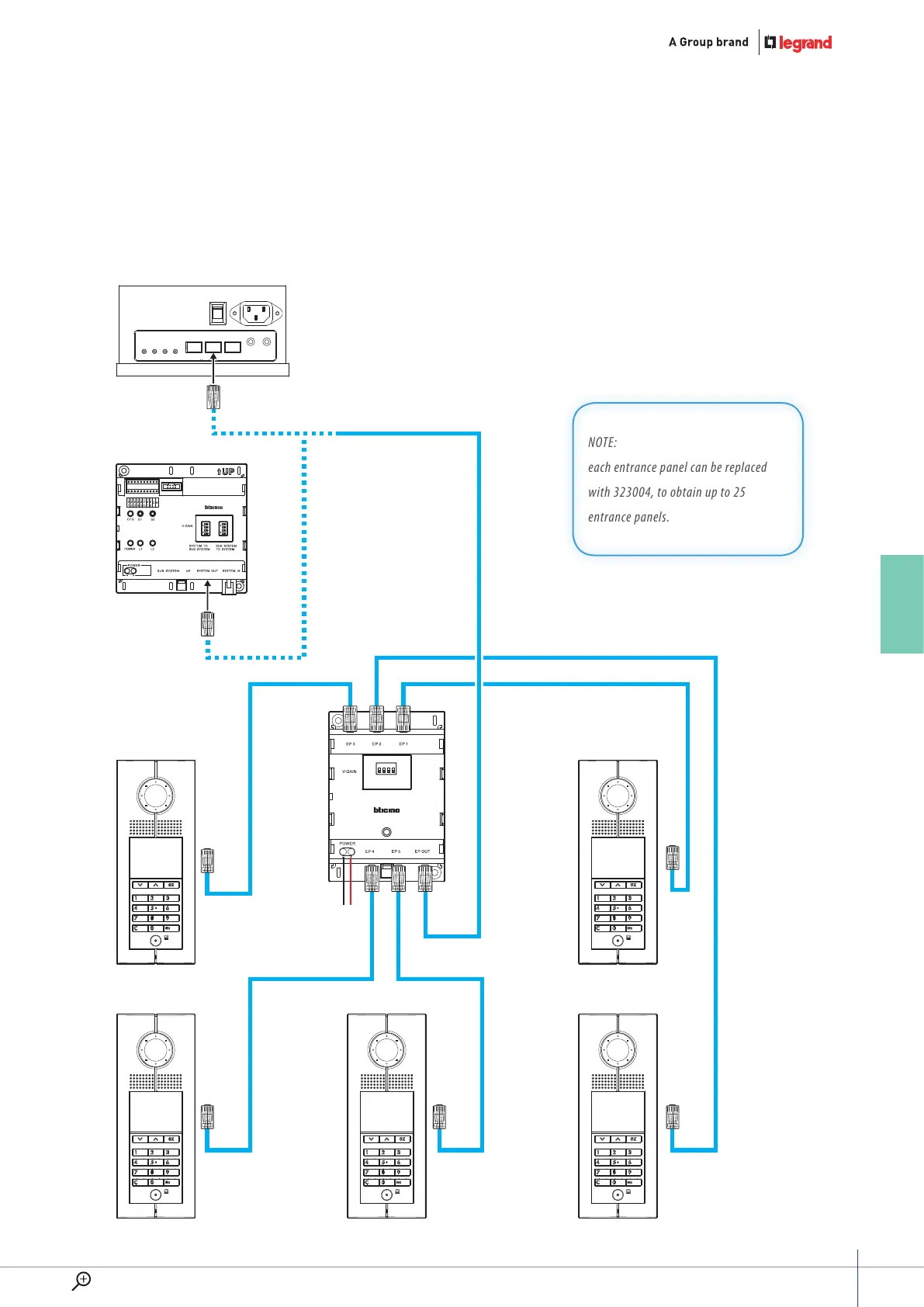
NOTE:
each entrance panel can be replaced
with 323004, to obtain up to 25
entrance panels.
B
D
C
A
+
–
–
+
ON
SD
1
2
3
4
ON
SD
1
2
3
4
1
2
3
4
POWER
–
+
T
o Riser shunt or Power supply
323005
323003
Entrance Panel
Entrance Panel
Entrance Panel
Entrance Panel
Entrance Panel
323004
Diagram 5
101
GUIDE
WWW
.LEGRAND.COM
108
110
Table of Contents
General Features
3
Table of Contents
5
World Presence & Technical Assistance
10
Software
11
Software and Services
12
Glossary
13
D45 System Introduction
14
The Main Devices
16
Entrance Panels
19
Products List and Main Features
20
System Composition
21
The Configuration
30
System Functions
31
General Rules for Installation
38
System Layout
38
System Cable
39
Standard RJ45 Connections for CAT5 Cable
41
RJ45 Connections
42
Entrance Panels and Indoor Handsets Installation
44
Entrance Panel Installation
45
Installation Method
45
Small Entrance Panel Installation
46
General Configuration Concept
47
System Configuration
47
EP Configuration Examples
51
Handset Configuration Examples
53
Accessory Configuration Examples
55
Lock Type and Distance Limits
63
Power Supply Installation Rules
65
Power Supply Check and Calculation
70
Maximum System Limits
75
Troubleshooting
80
Wiring Diagrams
84
Diagram 1
84
Handsets Riser Connection with Floor Shunt 323002
84
Diagram 2
86
Riser with 2 Branches Video Splitter 323007
86
Diagram 3
88
Backbone System with 1 Main Entrance Panel
88
Diagram 4
90
Backbone System with 1 Main Entrance Panel and Porter Switchboard 323001
90
Diagram 5
92
System with District Generator 323013
92
Diagram 6
94
Riser with Lift Control Interface 323017
94
Diagram 7
96
Town Villas System with Villa Shunt 323016
96
Diagram 8
98
System with D45 Interface and Fiber Optic Connection
98
Diagram 9
100
Wiring Diagrams - Variants
104
Diagram 1
104
IU Wired Connection + Alarm Connection
104
Connection Way for NC and no Contacts
105
IU Rear Side Connector
105
Diagram 2
106
Basic Apartment Interface Connection
106
Diagram 3
107
D45/2 Wire Interface Connection
107
Diagram 4
108
Apartment Interface Connection
108
Diagram 5
109
Entrance Panel Video Mixer Connection
109
Diagram 6
110
Wiring Diagrams - Door Lock Relay Connection
110
Diagram 7
110
Diagram 8
111
Entrance Pannel Auxiliary Power Supply Connection
111
Diagram 9
111
Power Supply Connection for Switchboard
111
Diagram 10
111
Connection of Entrance Hall Pushbutton to the Entrance Panel
112
Diagram 11
112
Floor Call Connection
112
Diagram 12
112
Back-Up Battery Connection
112
Diagram 13
112
IN/OUT Connection
113
Diagram 14
113
Single Family System with more then 1 Entry Panel
114
Diagram 15
114
Bt-322021
118
Bt-322052
119
Bt-323012
121
Catalogue
124
Technical Sheets
124
Technical Sheet Info
124
The Technical Sheets
128
5
Based on 1 rating
Ask a question
Give review
Questions and Answers:
Need help?
Do you have a question about the LEGRAND D45 SYSTEM and is the answer not in the manual?
Ask a question
LEGRAND D45 SYSTEM Specifications
General
Brand
LEGRAND
Model
D45 SYSTEM
Category
Intercom System
Language
English
Related product manuals
LEGRAND HPM D642/01
2 pages
LEGRAND On-Q
3 pages
LEGRAND 369339
6 pages
LEGRAND 369305
16 pages
LEGRAND 369425
8 pages
LEGRAND 369230
11 pages
LEGRAND 369315
16 pages
LEGRAND 369430
44 pages
LEGRAND 369300
16 pages
LEGRAND EASYKIT Plus
36 pages
LEGRAND EASYKIT Essential
32 pages
LEGRAND Easy Kit Connected
30 pages
 Loading...