Page 12
SURELIGHT
®
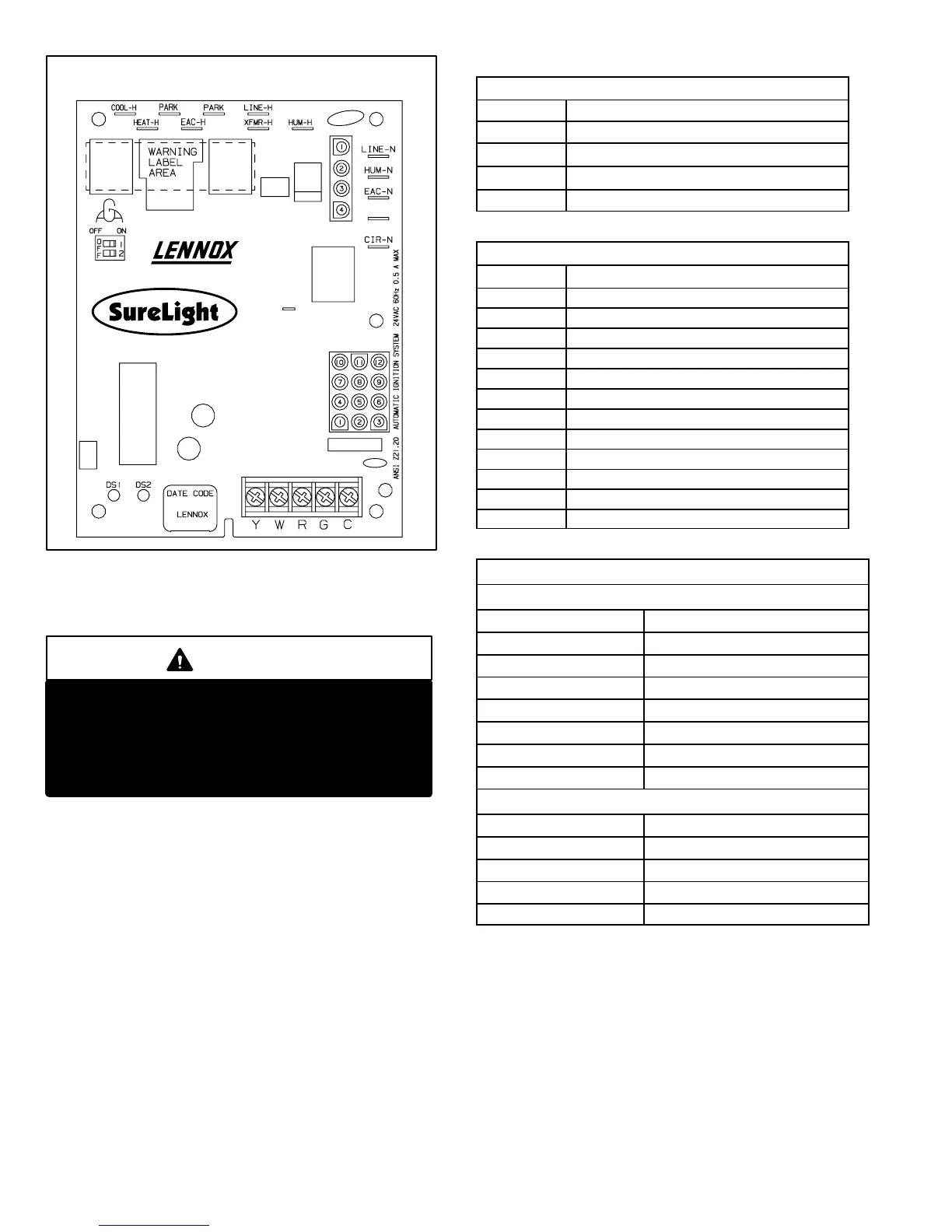
INTEGRATED CONTROL BOARD
32M88
FIGURE 6
J156
J58
XFMR-N
4. Ignition Control 78M47 & 100973−01 (A92)
G43UF−2 and later units
WARNING
Shock hazard.
Disconnect power before servicing. Control is
not field repairable. If control is inoperable, sim-
ply replace entire control.
Can cause injury or death. Unsafe operation will
result if repair is attempted.
The ignition control system consists of an integrated con-
trol board (figure 8 with control terminal designations in
table 7), ignitor (figure 9) and sensor (figure 10). The con-
trol board and ignitor work in combination to ensure fur-
nace ignition and ignitor durability. The control board con-
trols all major furnace operations. The control board also
features two LED lights (DS1 red and DS2 green) for trou-
bleshooting and two accessory terminals rated at (1) one
amp. The control board also features a (3) amp fuse for
overcurrent protection. Tables 5 and 6 show jack plug ter-
minal designations. See table 4 for troubleshooting diag-
nostic codes. The mini−nitride ignitor is made from a non−
porous, high strength proprietary ceramic material that
provides long life and trouble free maintenance. The con-
trol board continuosly monitors line voltage and maintains
the ignitor power at a consistent level to provide proper
lighting and maximum ignitor life.
TABLE 5
4−Pin Terminal Designation
PIN # FUNCTION
1 Combustion Air Inducer Line
2
Ignitor Line
3
Combustion Air Inducer Neutral
4
Ignitor Neutral
TABLE 6
12−Pin Terminal Designations
PIN # FUNCTION
1 High Limit Output
2 Not Used
3 24V Line
4 Not Used
5 Rollout Switch Out
6 24V Neutral
7 High Limit Input
8 Ground
9 Gas Valve Common
10 Prove Switch In
11 Rollout Switch In
12 Gas Valve Out
TABLE 7
TERMINAL DESIGNATIONS
120 Volt Hot
COOL Cool Speed
HEAT Heat Speed
PARK Park
PARK Park
EAC Electrconic Air Cleaner
XFMR Transformer
LINE Line
HUM Humidifier
120 Volt Neutral
CIRC Blower
XMFR Transformer
HUM Humidifier
LINE Line
Flame FS Flame Signal
Electronic Ignition (See Figure 5)
On a call for heat the ignition control board monitors the
combustion air inducer prove switch. The control board will
not begin the heating cycle if the prove switch is closed (by−
passed). Once the prove switch is determined to be open,
the combustion air inducer is energized. When the differen-
tial in the prove switch is great enough, the prove switch
closes and a 15−second pre−purge begins. If the prove
switch is not proven within 2−1/2 minutes, the control board
goes into Watchguard−Pressure Switch mode for a 5−min-
ute re−set period.
 Loading...


