Page 17
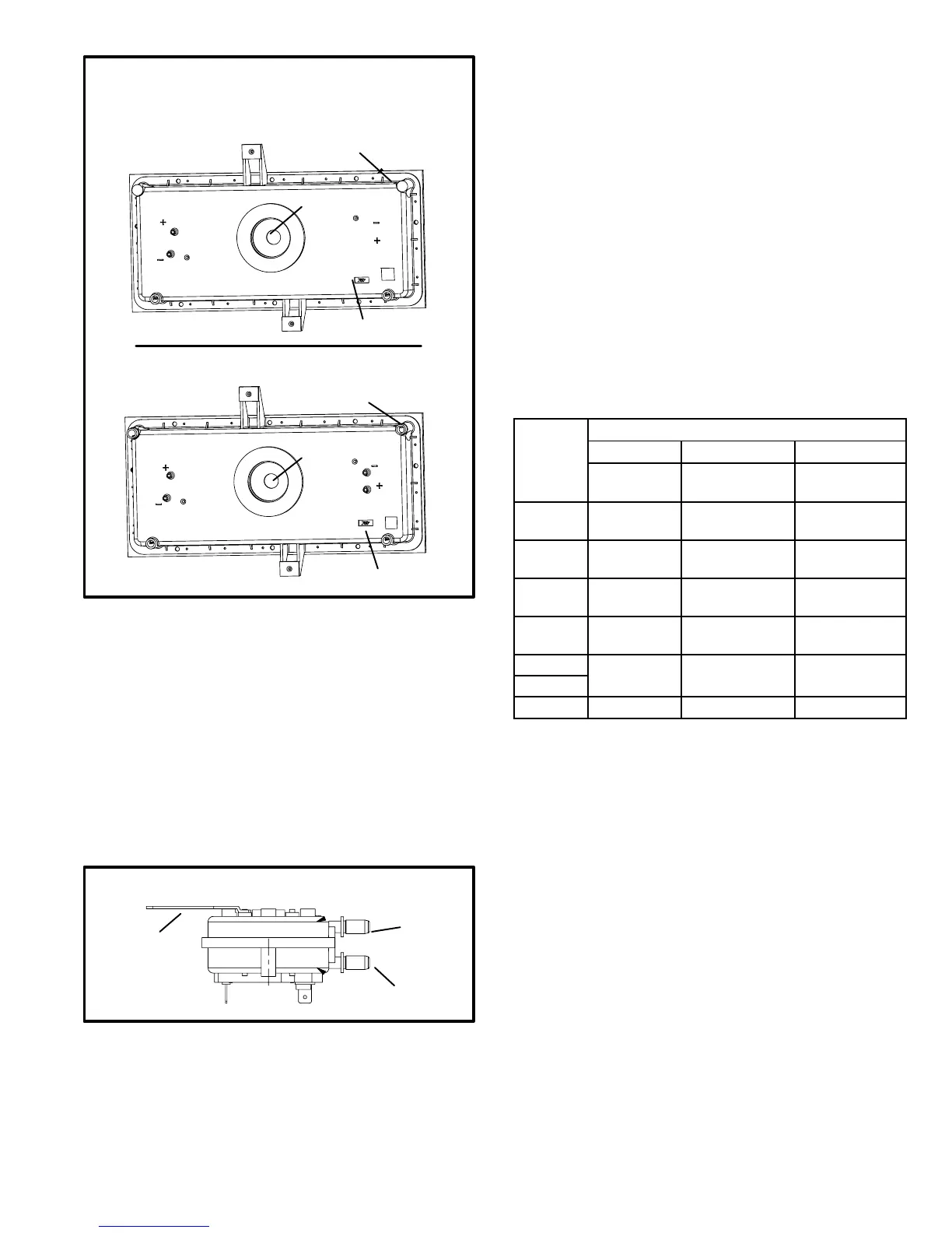
FIGURE 15
COLD END HEADER BOXES
G43
(gray in color)
G51 / G61
(black in color)
CLOSED DRAIN PORTS
(BOTH SIDES)
PRESSURE
TAPS
OPEN DRAIN PORTS
(BOTH SIDES)
PRESSURE
TAPS
PRESSURE
TAPS
ORIFICE SIZE ID
ORIFICE SIZE ID
ORIFICE
ORIFICE
10. Combustion Air Prove Switch (S18)
G43UF series units are equipped with a differential
prove switch located on the combustion air inducer
housing. See figures 16 and 17. One side of the switch is
gray (negative hose barb) and the other side is black (positive
hose barb). The switches monitor across the CAI orifice to in-
sure proper flow through the heat exchanger.
The switch is a SPST N.O. prove switch electrically con-
nected to the integrated control. The purpose of the switch is
to prevent burner operation if the combustion air inducer is not
moving enough air for proper combustion.
FIGURE 16
PROVE SWITCH (S18)
side view
bracket
terminals
negative (−) barb
gray
positive (+) barb
black
On start-up, the switch senses that the combustion air inducer
is operating. It closes a circuit to the ignition control when
the difference in pressure across the CAI orifice exceeds a
non−adjustable factory setting. If the switch does not suc-
cessfully sense the required differential, the switch can-
not close and the furnace cannot operate. If the flue or
air inlet become obstructed during operation, the switch
senses a loss of pressure differential and opens the circuit to
the ignition control. If the condensate line is blocked, water
will back up into the header box and reduce the pressure dif-
ferential across the switch. The prove switch opens if the dif-
ferential drops below the set point. See table 9.
Checks of pressure differential can aid in troubleshooting.
When measuring the pressure differential, readings should be
taken at the prove switch. Lack of differential usually indicates
problems in the intake or exhaust piping, but may indicate
problems in the heat exchanger, condensing coil, head-
er boxes, combustion inducer or other components.
TABLE 9
Altitude ft
−135
.65 (162) .55" (137) .45" (112)
*Set point is factory set and non−adjustable
**See table 20 for high altitude kits.
Measuring pressure differential
The differential pressure is the difference in pressure mea-
sured across the cold end header box orifice.
1 − Remove thermostat demand and allow unit to cycle
off.
2 − Install a tee in the negative (−) line and a tee in the positive
(+) line running from the prove switch to the cold end
header box.
3 − Install a manometer with hose from the negative (−)
side of the manometer to the tee installed in the nega-
tive (−) line and with hose from the positive (+) side of
the manometer to the tee in the positive (+) line.
NOTE − Both sides of the cold end header box are negative.
However the (+) port reads less negative pressure than the
(−) port.
 Loading...


