Page 14
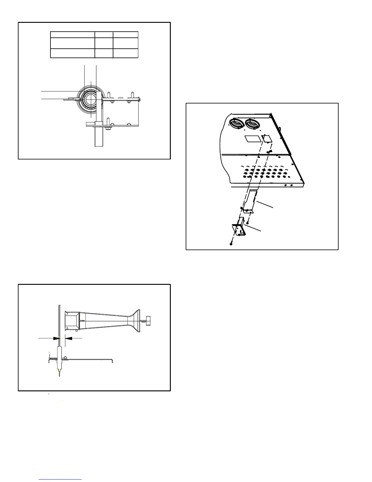
FIGURE 9
B"
Ignitor Location
BURNERS FRONT VIEW
MEASUREMENT IS TO I.D.
OF RETENTION RING
BRACKET
Silicon nitride
Mini Nitride
A" B"
.625 .406
.685 .306
A"
IGNITOR TYPE
2. Flame Sensor (Figure 10)
A flame sensor is located on the left side of the burner sup-
port. The sensor is mounted on the bottom burner box plate
and the tip protrudes into the flame envelope of the left−
most burner. The sensor can be removed for service with-
out removing any part of the burners. During operation,
flame is sensed by current passed through the flame and
sensing electrode. The ignition control allows the gas valve
to remain open as long as flame signal is sensed.
NOTE − The G43UF furnace contains electronic com-
ponents that are polarity sensitive. Make sure that the
furnace is wired correctly and is properly grounded.
FIGURE 10
5/16"
3. Primary Limit Control (S10)
Figure 11 shows the primary limit (S10) used on G43UF units
located in the heating vestibule panel. S10 is provided with a
shield on some models (figure 11) and must not be removed.
Note orientation of shield and limit if limit is replaced. When ex-
cess heat is sensed in the heat exchanger, the limit will open.
Once the limit opens, the furnace control energizes the
supply air blower and de−energizes the gas valve. The limit
automatically resets when unit temperature returns to nor-
mal. The switch is factory set and cannot be adjusted.
FIGURE 11
PRIMARY LIMIT LOCATION
limit faces shield
limit shield
090, −110 and
−135 only
4. Burners (Figure 12)
All units use inshot burners. Burners are factory set and do not
require adjustment. Burners can be removed as an assembly
for service. Burner maintenance and service is detailed in the
MAINTENANCE section of this manual. Each burner uses
an orifice which is precisely matched to the burner input. All
G43UF natural gas units are fitted with .089" sized orifices.
See table 20 or SPECIFICATIONS" tables for LP kits and
high altitude. The orifice is threaded into the burner man-
ifold.
The burner is supported by the orifice and will easily slide off
for service. A flame retention ring in the end of each burner
maintains correct flame length and shape and keeps the flame
from lifting off the burner head. In addition, the burner entrance
to each clamshell is fitted with a corbel cup (orifice) used to
direct the flow of combustion products.
NOTE − Do not use thread-sealing compound on the ori-
fices. Thread-sealing compound may plug the orifices.
 Loading...


