FIGURE 41
STATIC PRESSURE
TEST
G43UF UNIT
Page 37
C−External Static Pressure
1 − Measure tap locations as shown in figure 41.
2 − Punch a 1/4" diameter hole
in supply and return air ple-
nums. Insert manometer
hose flush with inside edge
of hole or insulation. Seal
around the hose with perma-
gum. Connect the zero end
of the manometer to the dis-
charge (supply) side of the system. On ducted sys-
tems, connect the other end of manometer to the return
duct as above. For systems with non−ducted returns,
leave the other end of the manometer open to the at-
mosphere.
3 − With only the blower motor running and the evaporator
coil dry, observe the manometer reading. Adjust blow-
er motor speed to deliver the air desired according to
the job requirements.
4 − Static pressure must not exceed 0.5" W.C.
5 − Seal around the hole when the check is complete.
D−Blower Speed Taps Leaded Motors
Blower speed tap changes are made on the SureLight con-
trol board. See figures 6 and 8. On G43UF−1 units, the
heating tap is connected to the HEAT−H" terminal and the
cooling tap is connected to the COOL−H" terminal. On
G43UF−2 and later units, the heating tap is connected to
the HEAT" terminal and the cooling tap is connected to t he
COOL" terminal. On all units the continuous blower tap is
the same as the heating tap and unused taps must be se-
cured on two dummy terminals labeled "PARK.
To change existing heat tap, turn off power then switch out
speed tap with tap connected to "PARK" . See unit diagram
for blower motor tap colors for each speed.
NOTE − Do not use red (low speed) motor lead for heating.
Leave on PARK terminal for 24B−070, 36C−090 and
48C−110 units.
NOTE − Operation of this furnace in heating mode (indoor
blower operating at selected heating speed) with an exter-
nal static pressure which exceeds 0.5 inches w.c. may re-
sult in erratic limit operation.
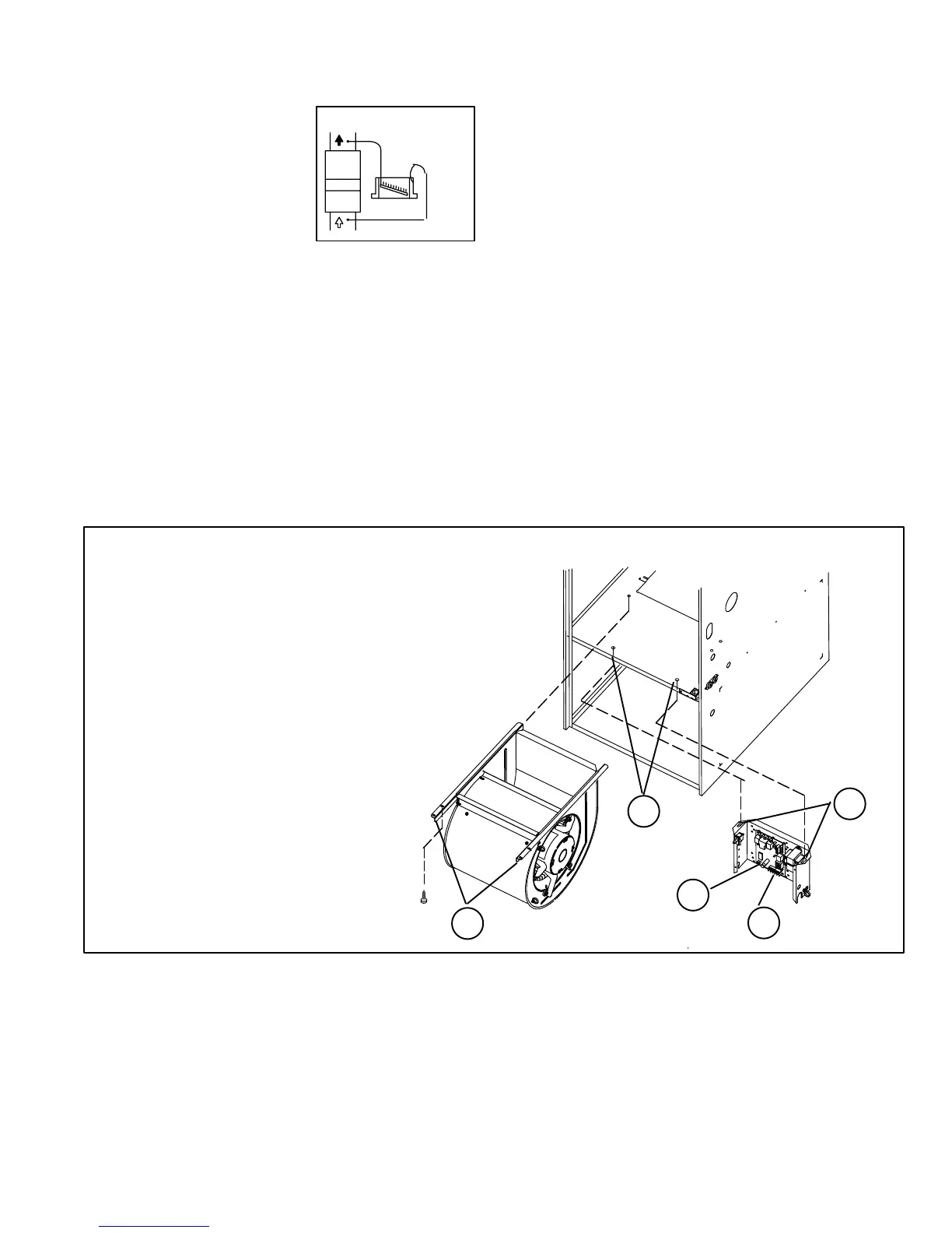
FIGURE 42
To Remove Blower:
Turn off line voltage power.
1 Disconnect thermostat wiring con-
nections.
2 Disconnect blower leads from control
board and secondary limt wires.
3 Loosen screws (2) and remove con-
trol box from unit. Holes are slotted so
screws do not need to be removed.
4 Remove screws (2) and remove
blower from unit.
G43UF BLOWER REMOVAL
4
2
3
1
3
 Loading...


