Page 13
After the 15−second pre−purge period, the ignitor warms up
for 20 seconds during which the gas valve opens at 19 sec-
onds for a 4−second trial for ignition. The ignitor remains
energized for the first 3 seconds during the 4 second trial. If
ignition is not proved during the 4−second period, the con-
trol will try four more times with an inter purge and warm−up
time between trials of 35 seconds. After a total of five trials
for ignition (including the initial trial), the control goes into
Watchguard−Flame Failure mode. After a 60−minute reset
period, the control will begin the ignition sequence again.
The control board has an added feature of ignitor power
regulation to maintain consistent lighting and longer ignitor
life under all line voltage conditions.
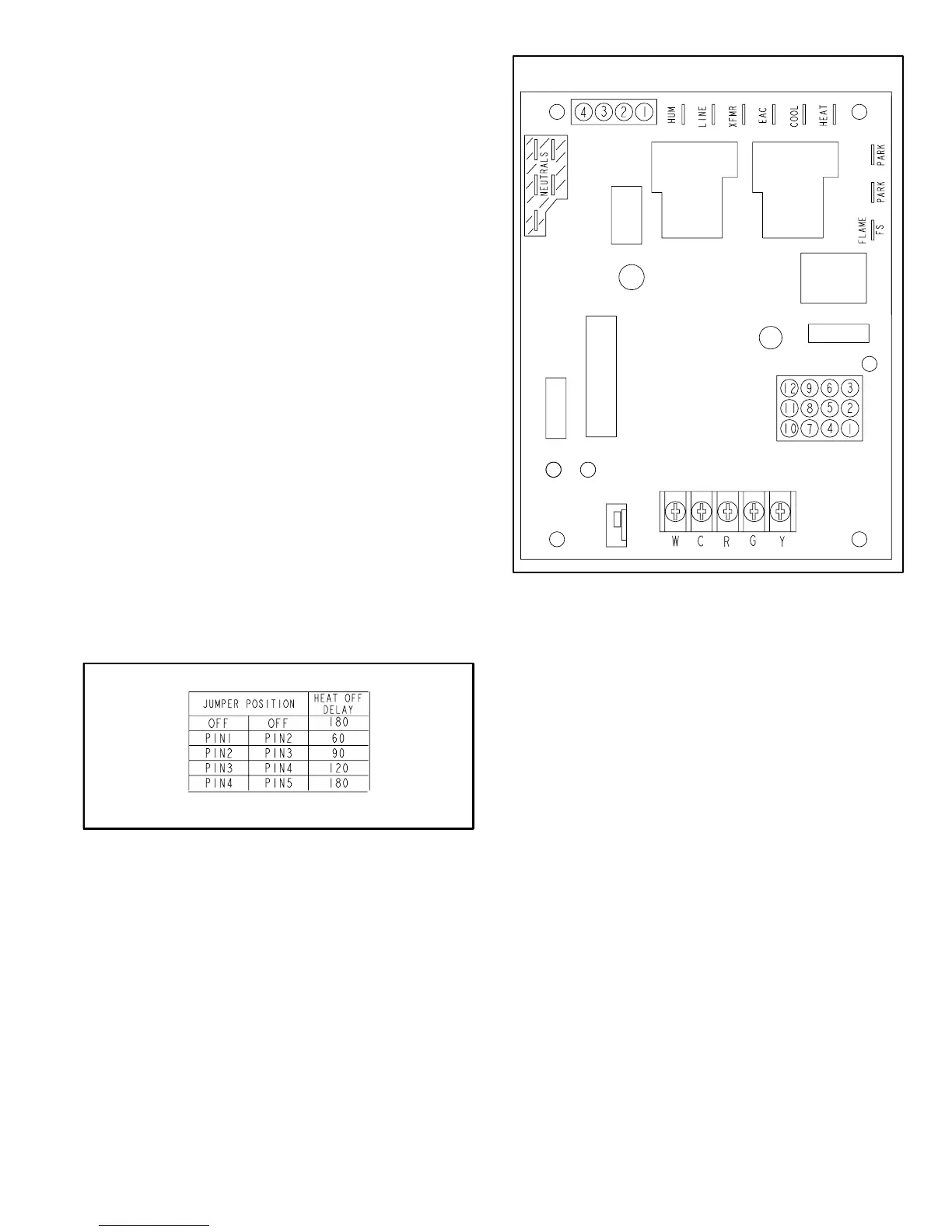
Fan Time Control
The fan on time of 45 seconds is not adjustable. Fan off
time (time that the blower operates after the heat demand
has been satisfied) can be adjusted by moving the jumper
to a different setting. The unit is shipped with a factory fan
off setting of 90 seconds. For customized comfort, monitor
the supply air temperature once the heat demand is satis-
fied. Note the supply air temperature at the instant the
blower is de−energized. Adjust the fan−off delay to achieve
a supply air temperature between 90° − 110° at the instant
the blower is de−energized. (Longer delay times allow for
lower air temperature, shorter delay times allow for higher
air temperature). See figure 7.
Board 100973−01 only has a 45 second fan off delay after
cooling demand is met. This timing is factory set and can-
not be adjusted.
FAN-OFF TIME ADJUSTMENT
To adjust fan−off timing, reposition jumper across pins to
achieve desired setting.
FIGURE 7
IGNITION CONTROL BOARD
FIGURE 8
DS2
GREEN
DS1
RED
C−Heating Components
Combustion air inducer (B6), primary limit control (S10),
SureLight ignitor, burners, flame rollout switch (S47), gas
valve (GV1), combustion air prove switch (S18), and clam-
shell heat exchangers are located in the heating compart-
ment. The heating compartment can be accessed by re-
moving the burner access panel.
1. Ignitor (Figure 9)
The SureLight ignitor used on G43UF−1 units, is made of
durable silicon nitride. The board finds the lowest ignitor
temperature which will successfully light the burner, thus
increasing the life of the ignitor. Due to this feature of the
board, voltage cannot be measured. The check ignitor,
measure its resistance. A value of 10.9 to 19.7 ohms indi-
cates a good ignitor.
The ignitor used on G43−2 and later units use a mini−nitride
ignitor made from a proprietary ceramic material. Ignitor
longevity is enhanced by controlling the voltage to the igni-
tor. The check ignitor, measure its resistance. A value of 50
to 450 ohms indicates a good ignitor.
 Loading...


