Page 50
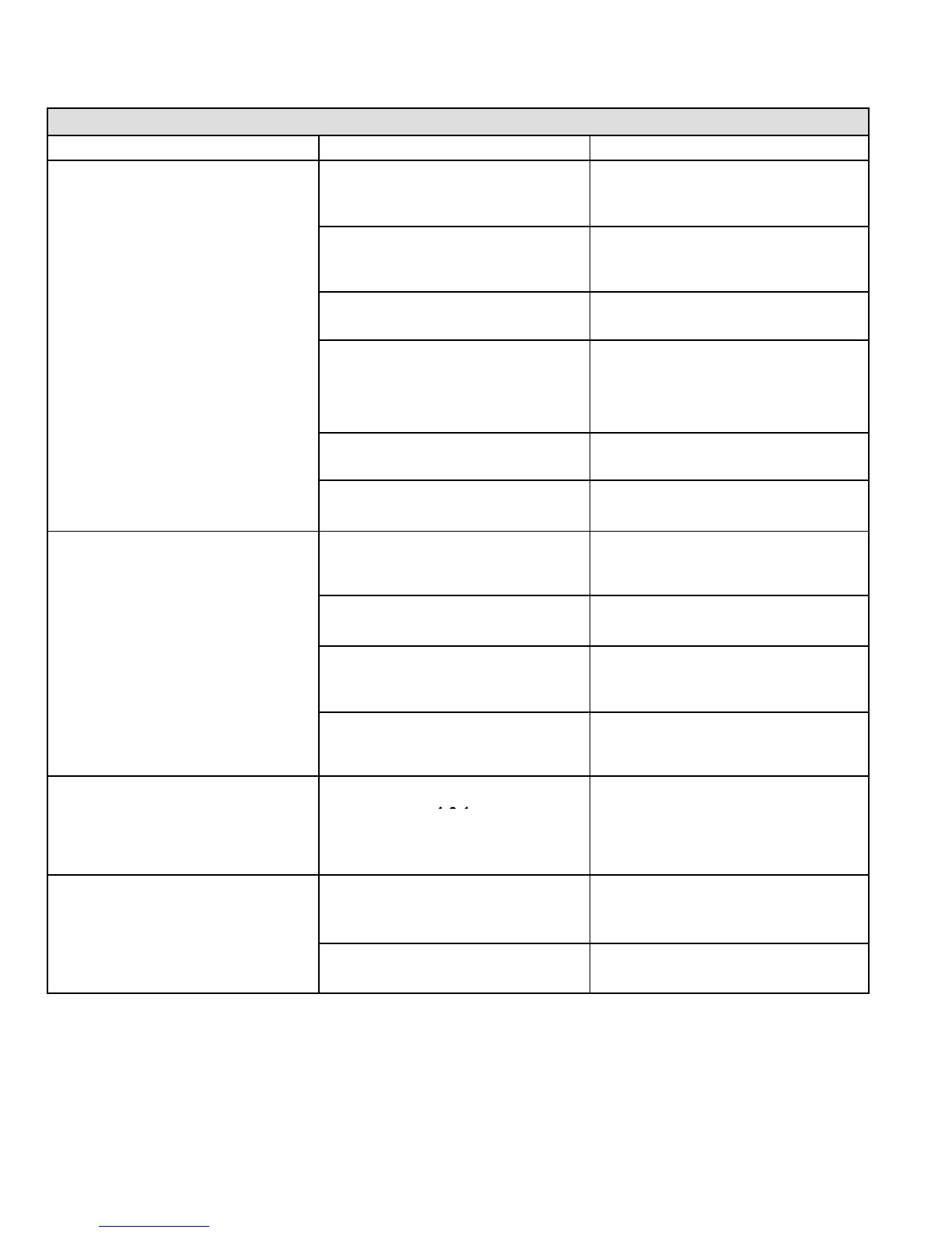
VIII−Ignition Control Board Troubleshooting Chart
UPON INITIAL POWER UP, REMOVE ALL THERMOSTAT DEMANDS TO THE UNIT
PROBLEM: 1 UNIT FAILS TO OPERATE IN THE COOLING, HEATING, OR CONTINUOUS FAN MODE
Condition Possible Cause Corrective Action / Comments
1.1
− Both diagnostic lights fail to light up.
1.1.1
Main voltage 120V not supplied to unit.
ACTION 1 − Check 120V main voltage.
Determine cause of main power failure.
LED#1−Off
LED#2−Off
1.1.2
Miswiring of furnace or improper con-
nections.
ACTION 1 − Check for correct wiring of 120V to
power make up box and transformer.
ACTION 2 − Check 24V wiring to control board.
1.1.3
Blown fuse
ACTION 1 − Replace fuse.
ACTION 2 − If fuse still blows, check for short.
1.1.4
Door interlock switch failure.
ACTION 1 − Check that door switch is activated
when door is closed.
ACTION 2 − Check wire connections to switch, re-
place loose connectors.
ACTION 3 − Check continuity of switch in closed
position. Replace if defective.
1.1.5
Transformer Failure.
ACTION 1 − Check that transformer output is
24V. Replace if defective.
1.1.6
Failed control board.
ACTION 1 − If all the above items have been
checked, replace board.
1.2
− Diagnostic lights flash the roll−out
code.
1.2.1
Roll−out switch open.
ACTION 1 − Manually reset the roll−out switch
by pushing the top button.
ACTION 2 − Determine the cause of the roll−out
switch activation before leaving furnace.
.
120V field connection.
1.4
1.4.1
Open combustion air inducer motor
circuit.
ACTION 1 − Check for 120V to combustion air
inducer. If no power, check wire and connec-
tions.
LED#1−Slow Flash
LED#2−Slow Flash
1.4.2
Failed combustion air inducer motor.
ACTION 1 − If power is present at blower, replace
blower.
 Loading...


