Page 16
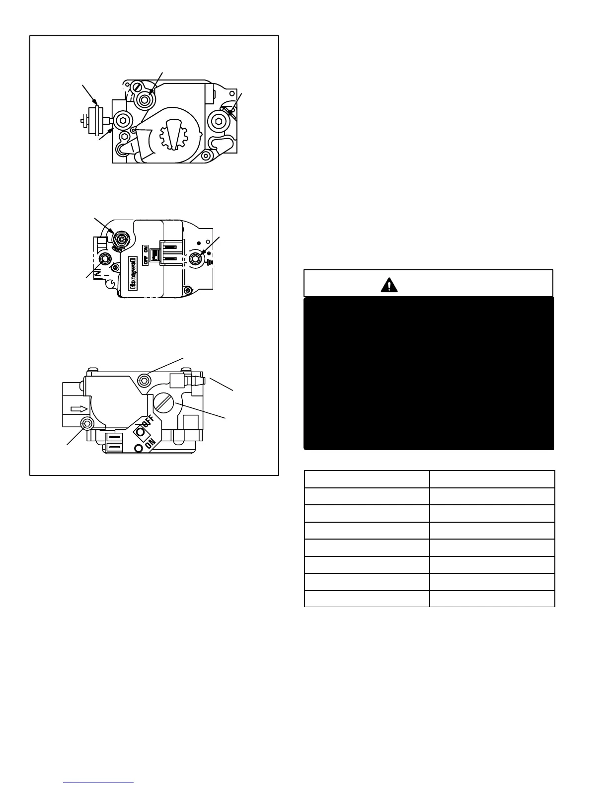
FIGURE 14
HONEYWELL VR8205 SERIES GAS VALVE
WHITE RODGERS 36G SERIES GAS VALVE
GAS VALVE SHOWN IN OFF POSITION
MANIFOLD
PRESSURE
ADJUSTMENT
SCREW
MANIFOLD PRESSURE
OUTLET POST
LINE PRESSURE
INLET POST
REFERENCE
TO BURNER
BOX
MANIFOLD
PRESSURE
OUTLET
INLET
PRESSURE
PORT WITH
INLET TAP
FITTING
PRESSURE
SWITCH
(LP ONLY)
ON
OFF
BARBED
FITTING
HONEYWELL VR8205 SERIES GAS VALVE
(With On/Off Switch)
GAS VALVE ON/OFF SWITCH SHOWN IN ON POSITION
MANIFOLD
PRESSURE
OUTLET
MANIFOLD
PRESSURE
ADJUSTMENT
SCREW
(under cap)
LINE PRESSURE
INLET POST
9. Combustion Air Inducer (B6)
& Cold End Header Box
All G43UF units use a combustion air inducer to move air
through the burners and heat exchanger during heating
operation. The blower uses a shaded pole 120VAC mo-
tor. The motor operates during all heating operation and is
controlled by burner ignition control A3. Blower operates
continuously while there is a call for heat. The burner igni-
tion control will not proceed with the ignition sequence until
combustion air inducer operation is sensed by the proving
switches.
The CAI is installed on the cold end header box. The cold
end header box is a single piece made of hard plastic.
The box has an internal channel where the combustion
air inducer creates negative pressure at unit start up. The
channel contains an orifice used to regulate flow created
by the CAI. The box has pressure taps for the CAI prove
switch hoses. The prove switch measure the pressure
across the CAI orifice or difference in the channel and the
box. A window is provided on the bottom right hand side
of the box to indicate orifice size. See figures 15 and 17.
See table 8 for orifice size per unit. If replacement is
necessary the gaskets used to seal the box to the
vestbule panel and the CAI to the box, must also be
replaced.
WARNING
CARBON MONOXIDE POISONING HAZARD
Do not install a header box designed for the G51 or
G61 furnace onto a G43 furnace. Header boxes for
G51 and G61 furnaces are equipped with open
drain ports in the upper corners of the box, which
allow bypass of the proper flow of combustion air
to the burners. Differences in header box are
shown in figure 15.
When replacing a G43 header box, ensure that the
replacement box is equipped with the same orifice
size and number of drain and pressure ports as the
original. G43 header boxes are GRAY in color. G51
and G61 series header boxes are BLACK in color.
TABLE 8
G43UF Unit
C.A.I. Orifice Size
−045−1 to −6 .750"
−045−7 and later .703"
−070−7 and later .922"
−070−1 to −6 .969"
−090 1.063"
−110 1.344"
−135 1.625"
 Loading...


