Page 40
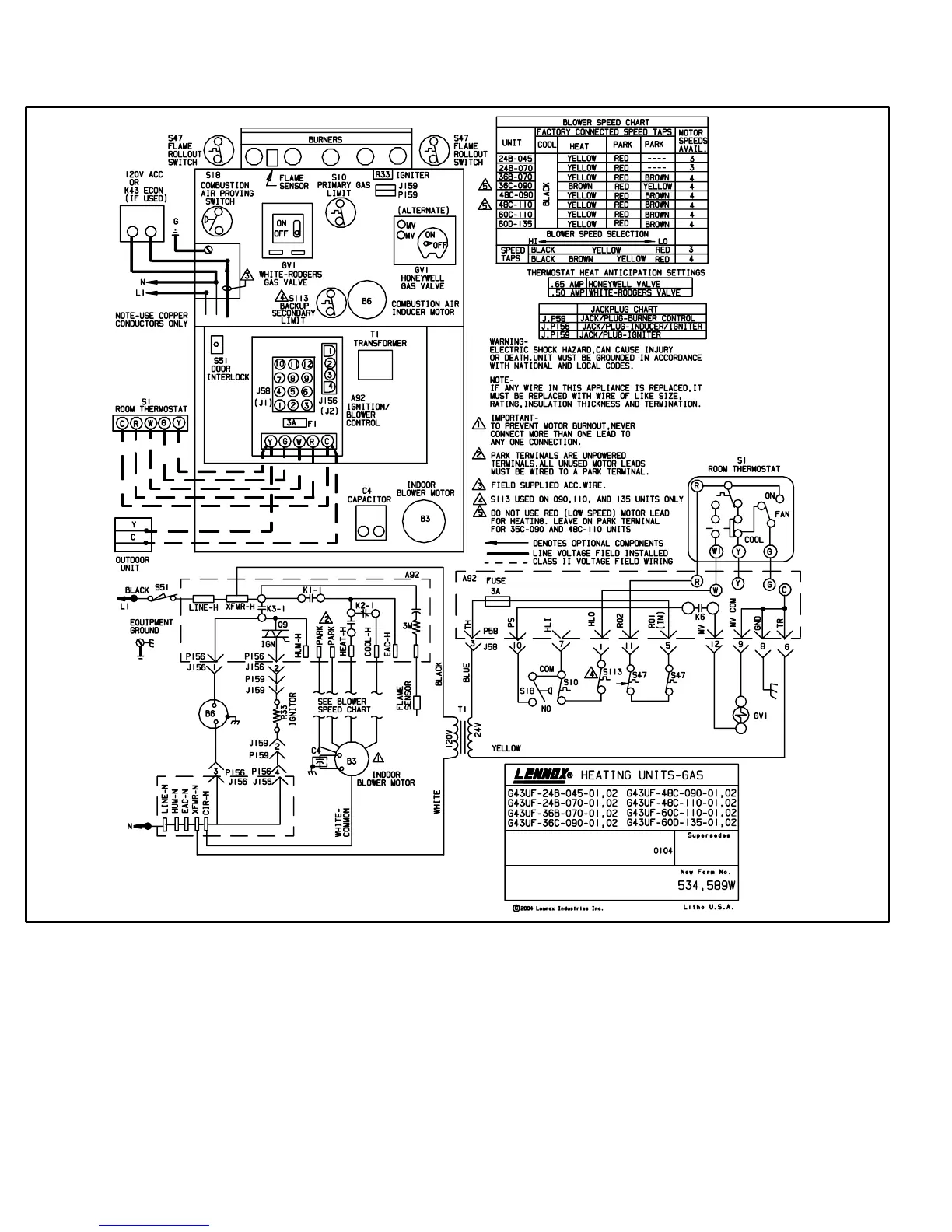
VII−WIRING DIAGRAM AND SEQUENCE OF OPERATION
1 − When there is a call for heat, W1 of the thermostat en-
ergizes W of the furnace control with 24VAC.
2 − S10 primary limit switch and S47 rollout switch are
closed. Call for heat can continue.
3 − The integrated contol (A92) energizes combustion air
inducer B6. Combustion air inducer runs until S18
combustion air prove switch closes (switch must close
within 2−1/2 minutes or control goes into 5 minute
Watchguard Pressure Switch delay). Once S18
closes, a 15−second pre−purge follows.
4 − The integrated control (A92) energizes ignitor. A
20−second warm−up period begins.
5 − Gas valve opens for a 4−second trial for ignition
6 − Flame is sensed, gas valve remains open for the heat
call.
7 − After 45−second delay, the integrated control (A92) en-
ergizes indoor blower B3.
8 − When heat demand is satisfied, W1 of the indoor ther-
mostat de−energizes W of the integrated control which
de−energizes the gas valve. Combustion air inducer
B6 continues a 5−second post−purge period, and in-
door blower B3 completes a selected OFF time delay.
 Loading...


