Page 36
I−High Altitude
NOTE − In Canada, certification for installations at eleva-
tions over 4500 feet (1372 m) is the jurisdiction of local au-
thorities.
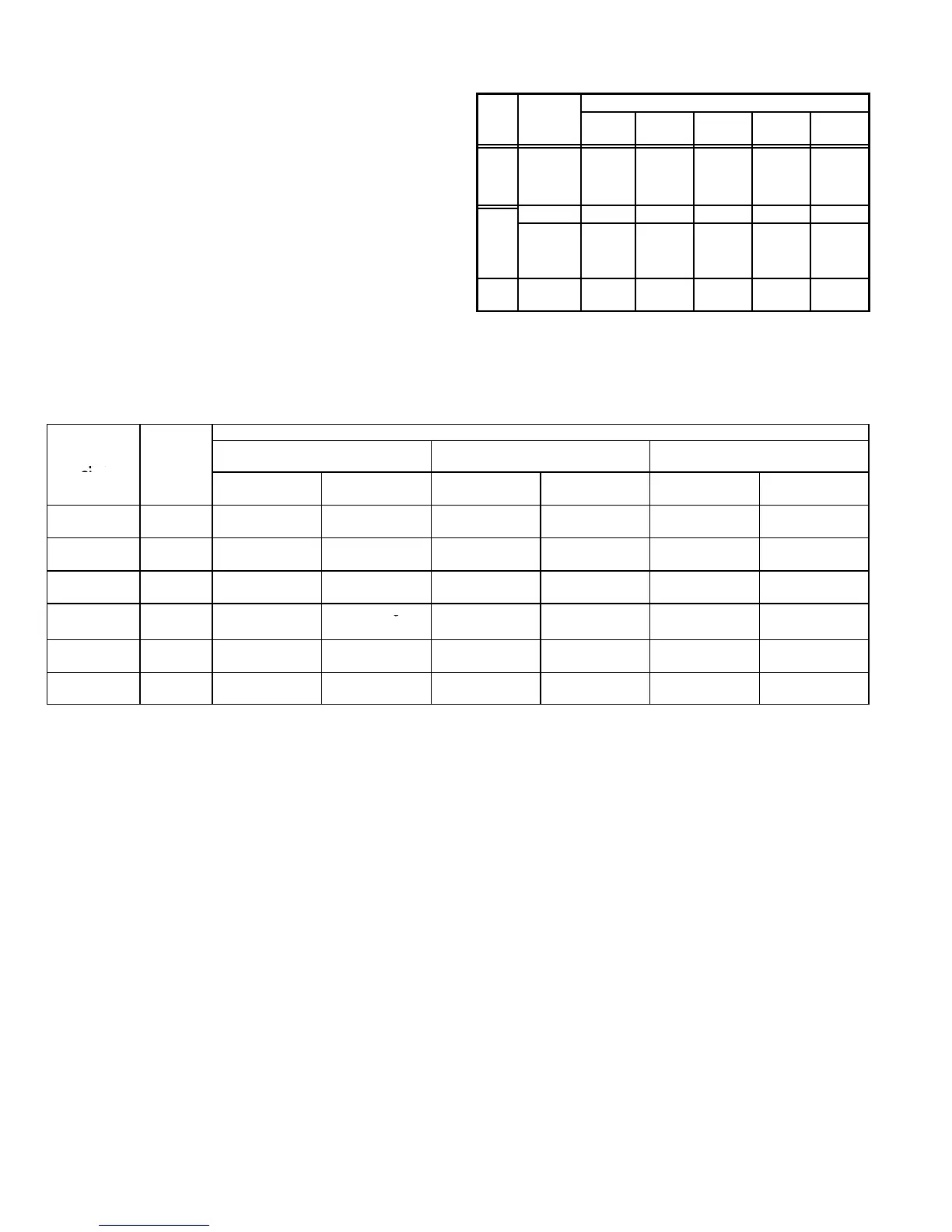
The manifold pressure may require adjustment to ensure
proper operation at higher altitudes. Refer to table 19 for
proper manifold pressure settings at varying altitudes.
Table 20 lists required pressure switch changes and con-
version kits at varying altitudes.
The combustion air pressure switches are factory−set and
require no adjustment.
TABLE 19
Manifold Pressure (Outlet) inches w.c.
Model
Altitude (feet)
Fuel
and later
LPG 83M74 No Change 83M74 56M04 83M75 60M35
Pressure switch is factory set. No adjustment necessary. All models use the factory installed pressure switch from 0−4500 feet (0−1370 m).
V−TYPICAL OPERATING CHARACTERISTICS
A−Blower Operation and Adjustment
NOTE− The following is a generalized procedure and
does not apply to all thermostat controls.
1 − Blower operation is dependent on thermostat control
system.
2 − Generally, blower operation is set at thermostat sub-
base fan switch. With fan switch in ON position, blower
operates continuously. With fan switch in AUTO position,
blower cycles with demand or runs continuously while
heating or cooling circuit cycles.
3 − In all cases, blower and entire unit will be off when the
system switch is in OFF position.
B−Temperature Rise
Temperature rise for G43UF units depends on unit input,
blower speed, blower horsepower, filter resistance and
installed duct system resistance. The blower speed must
be set for unit operation within the range of TEMPERA-
TURE RISE °F" listed on the unit rating plate.
To Measure Temperature Rise:
1− Place plenum thermometers in the supply and return air
plenums. Locate supply air thermometer in the first hori-
zontal run of the plenum where it will not pick up radiant
heat from the heat exchanger.
2 − Set thermostat to highest setting.
3 − After plenum thermometers have reached their high-
est and steadiest readings, subtract the two readings.
The difference should be in the range listed on the unit
rating plate. If the temperature is too low, decrease
blower speed. If temperature is too high, first check the
firing rate. Provided the firing rate is acceptable, in-
crease blower speed to reduce temperature. To
change blower speed taps see the Blower Speed Taps
section in this manual.
 Loading...


