11
PIAB = [(Required CFM - Minimum CFM) / (Maximum CFM - Minimum CFM)] * 100
Sample CFM
RequiredMinimum Maximum Minimum
Sample PIAB = ([___920 -450 ] / [ 2000 -450 ]) x 100
==
Sample PIAB =([ 470 ] / [1550]) x 100
=
Sample PIAB =[0.303] x 100 = 30 %
Figure 10. PIAB Calculation Example
example
CFM
values
Require
d
CF
M
CFM
Zon
e
1
Zone
2
Zone
3
Zone
4
Min.
Max.
1020
1500
720
OFF
720
2200*
*High cool jumper settin
g
PIA
B
formula
100
(R
e
q’
d
CFM
−
min. C
FM
)
(Max. CFM
−
min. CFM
)
x
U
s
i
ng e
x
a
m
p
l
e v
a
lue
s
abo
v
e,
fi
nd
PIAB
f
o
r
Zone 1
:
PIA
B
(
1
02
0
-
7
2
0
)
= 30
0
=.20
.
.
.
.
..
.
..
.
.
.
..
.
.
.
.
.
...
.
..
.
..
.
(2220 - 720) =150
0
.
.
.
.
..
.
..
.
.
.
..
.
.
.
.
.
.
.
.
.
PIAB Jumper setting
%
.20 x 10
0
20%
.
.
.
.
..
.
.
.
..
.
.
...
.
..
.
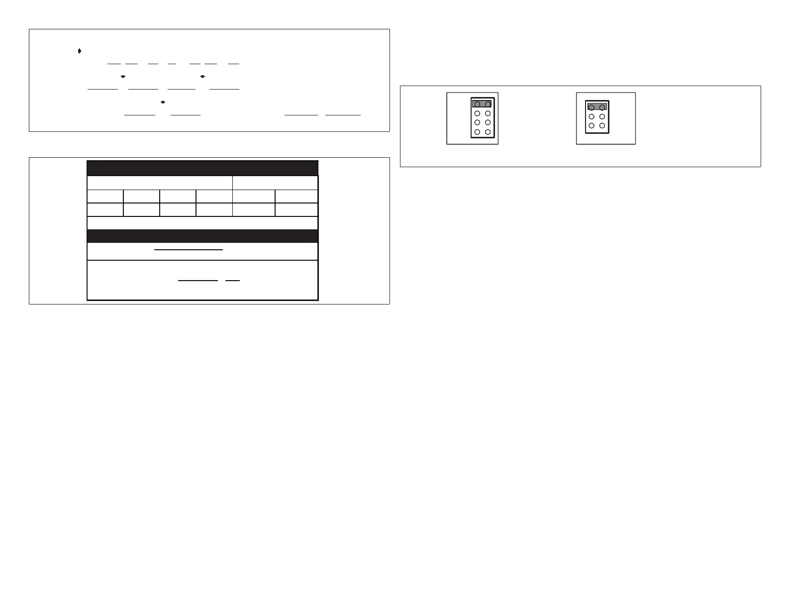
Figure 11. Determine PIAB Jumper Settings
1.10.6. Continuous Air Reduction Jumpers
During continuous fan mode without either a heating or cooling demand, the blower
runs at the total percentage of the CFM jumper settings of the zones calling for
continuous fan (not to exceed 100% of blower capacity). A continuous air reduction
jumper allows the blower speed to be reduced by a percentage during continuous
fan mode.
The selections are 75%, 50%, 25% and 0%. At the factory, the jumper is set on
0%. Set the jumper to the position equal to the amount of continuous air reduction
desired.
NOTE: If the calculations using a reduction percentage indicated a resulting CFM
lower than the blower’s minimum CFM rating, the blower will deliver its
minimum CFM
1.10.7. Heating Air Reduction Jumpers
NOTE: For heat pump applications, ALWAYS set the jumper on 0%. High head
pressures may result if air is reduced during heating mode.
NOTE: For use in warm-climate areas where units have high cooling capacity with
low heat capacity, ALWAYS set the jumper on 0%.
The heating air reduction jumper enables the blower speed, during heating only, to
run at a reduced rate compared to the cooling blower speed.
The selections are 40%, 20% and 0%. Jumpers are set to 0% from the factory.
Set the jumper to the position equal to the amount of heating air reduction desired.
CONTINUOUSHEATING
0%
20%
40%
75%
50%
0%
25%
factory
settings
shown
heating jumper
Must be set on 0%
for heat pump
application
Figure 12. Heating Air Reduction Jumpers
1.10.8. Heat/Cool Staging
Heating/Cooling staging jumpers prevent any rapid staging of the equipment. This
section shows the recommended settings for heating/cooling staging temperatures
andexplainsthetemperaturedifferentialsfordifferentequipmentcongurations.
In the diagrams, sine waves indicate which stage operates during the rise and
fall of discharge air temperature for the different heating/cooling staging jumpers.
Recommended jumper settings are shown in bold type.
1.10.8.1. Heating Staging Temperature Jumper
Heating Staging temperature jumpers are used to set the temperature at which the
secondstageheatingequipmentcomesON.Itsselectionsrangefrom85-130(°F).
Thesettinghasabuilt-indifferentialof20°F(exceptasdescribedwhen140DAS
jumper is used). During operation, when the discharge air temperature falls below
the jumper setpoint, 2nd-stage heating begins. If the discharge air temperature
reaches the differential temperature, 2nd-stage operation ceases and 1st-stage
heating resumes until the temperature again falls below the jumper set point.
NOTE: For SLP98 furnaces only, the furnace ignition control will automatically
adjust ring rate without a second stage heat demand to match the blower
airow (CFM) requested by the Harmony III zoning system.
HeatPump(range:85-110°F,recommended:90).Themaximumdischargeair
temperatureatwhichtheheatpump/electricheatisallowedtorunisxedat135°F.

 Loading...


