5
allows conditioning of different zones within a residence while using a single HVAC
system. The zone control system operates in two modes: central control (vacation
mode) or zone control. LEDs on the zone control panel indicate the current
operating mode.
When the system is in the central control mode, a demand from the central control
thermostat results in conditioned air being directed to all of the zones. In this mode,
zone 1 thermostat is designated as the controlling thermostat; other thermostats
are not used. When the system is in the zone control mode, a zone is conditioned
only upon demand from that zone’s thermostat. The zone control system is ideal for
retrotapplicationsaswellasnewconstruction.Thesystemcontrolstheairvolume,
eliminating the need for bypass dampers in most applications. The homeowner
controls the system using zone thermostats to make comfort settings for each
zone. A programmable thermostat should be used to provide a specialized heating
and cooling sequence. While the system is in the zone mode, a programmable
thermostat controls the temperature for its particular zone.
1.5. ResidentialZoneControlSystem-OverviewofField
Wiring
VARIABLE SPEED
FURNACE OR AIR
HANDLER
ZONE 1
ZONE 2
*ZONE 4
POWER
THERMOSTAT (ZONE 1 OR CENTRAL CONTROL
THERMOSTAT WHEN IN VACATION MODE)
ZONE DAMPER
THERMOSTAT
(ZONE)
CONDENSING
UNIT OR HEAT
DOOR UNIT
TRANSFORMER TO POWER
MOSTATS AND DAMPERS;
ALSO POWERS HZA CONTROL
WHEN EDA IS USED)
THERMOSTAT
(ZONE)
LEGEND -
A Five wire low voltage — 18 ga. minimum
B Two wire low voltage OR Three wire if Power-open, Power-closed — 18 ga. minimum
C INDOOR UNIT: Up to nine wire low voltage — 18 ga. minimum
D OUTDOOR UNIT:
- Two (3, if LSOM equipped unit) wire low voltage (single‐stage condensing unit or EDA) 18 ga. minimum
- Three (4, if LSOM equipped unit) wire low voltage (two‐stage condensing unit) 18 ga. minimum
- Up to seven wire low voltage (single‐stage heat pump outdoor unit) 18 ga. minimum
- Up to eight wire low voltage (two‐stage heat pump outdoor unit) 18 ga. minimum
E Two wire low voltage (discharge air sensor) 18 ga. minimum
F Two wire low voltage (pressure switch, heat pump only) — 18 ga. minimum
G Two wire — 18 ga. minimum
H Refer to the Humiditrol® Zoning Accessory (HZA) for wiring requirements.
*NOTE - Zone 3 and zone 4 not available with single‐stage outdoor unit.
OUTDOOR
THERMOSTAT /
BALANCE
POINT SENSOR
ZONE CONTROL
SYSTEM PANEL
A
B
DISCHARGE
AIR SENSOR
E
C
D
F
ZONE DAMPER
G
*ZONE 3
THERMOSTAT
(ZONE)
ZONE DAMPER
ZONE DAMPER
HUMIDITROL
®
ENHANCED
DEHUMIDIFICATION
ACCESSORY
HUMIDITROL
®
ZONING
ACCESSORY (HZA)
OPTIONAL
H
A
B
B
A
B
A
B
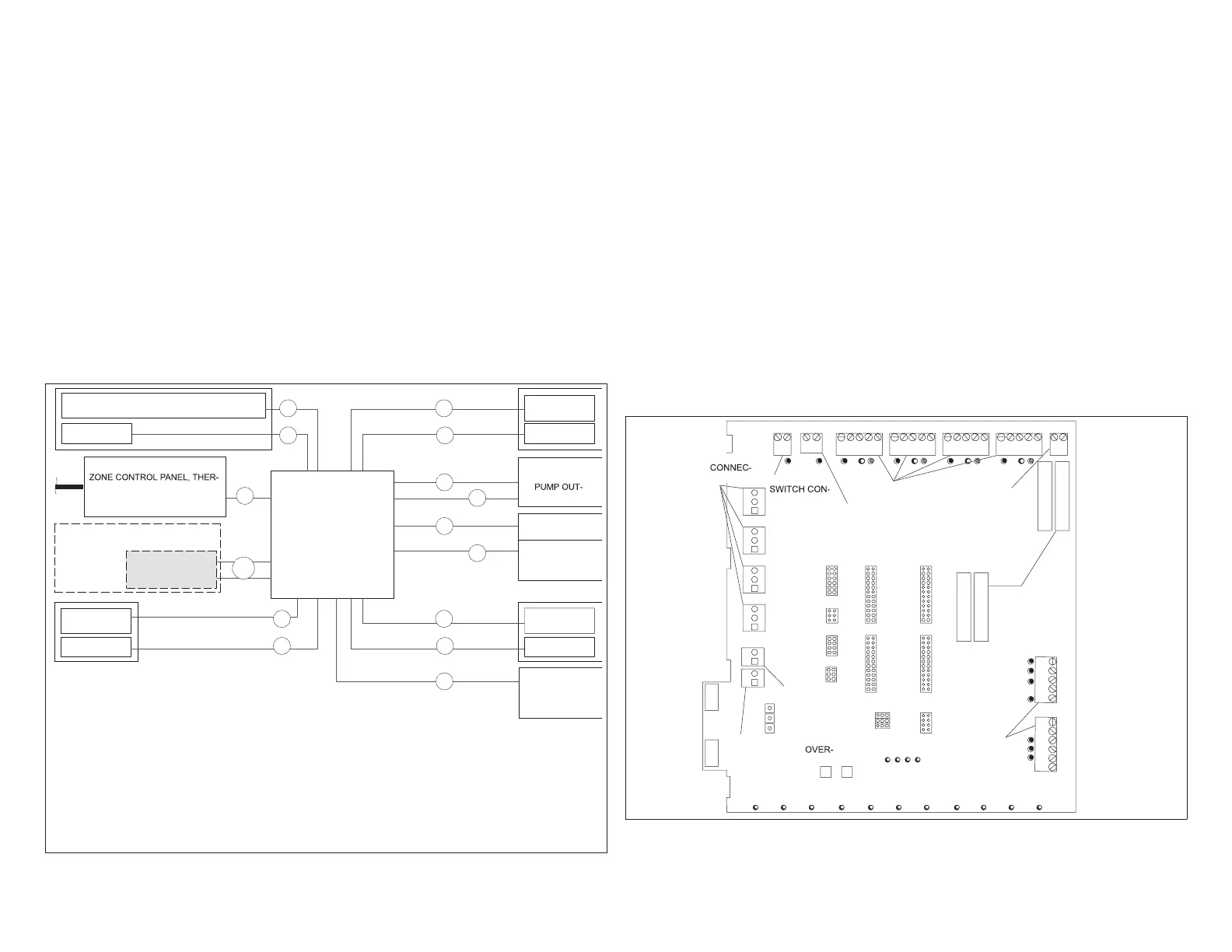
Figure 1. Field Wiring
1.6. System Components
The Harmony III zoning system consists of the following (required):
• Harmony III zoning system zone control panel (included)
• Discharge Air sensor (included)
• Thermostats (one for each zone; ordered separately)
• 24VAC Power Transformer(s) (ordered separately)
• Dampers (ordered separately)
• Pressure Switch and Tee with Schrader valve (for Heat Pump systems; ordered
separately)
• Balance Point Sensor (Optional for Dual Fuel systems)
• Defrost Tempering Kit (Optional for Dual Fuel systems)
• Remote Vacation Switch (optional; ordered separately)
1.6.1. Zone Control System
The Harmony III zoning system monitors electrical signals and directs control
signals between thermostats, dampers, and HVAC equipment.
JUMPERS:
STAGING
TEMP`
HEATING--
COOLING--
AIR
REDUCTION
CONT.--
HEATING--
EQUIPMENT
CONNECTIONS
THERMOSTAT
CONNECTIONS
24VAC
CONNECTIONS
PIAB
JUMPERS
SYS CONFIG AND
E-HEAT JUMPERS
DIAGNOSTIC
LEDS
TIME
DELAY
RIDE
FAULT
RECALL
OUTDOOR THERMOSTAT /
BALANCE POINT SENSOR
CONNECTIONS
PRESSURE
NECTIONS
DISCHARGE
AIR SENSOR
CONNECTIONS
DAMPER
TIONS
FUSES
SYSTEM OPERATION LEDS
REMOTE
VACATION
SWITCH;
CONNECTIONS
FOR HZA
Figure 2. Harmony III Zoning System Zone Control Panel

 Loading...


