7
1.7. Installation Planning and Selecting Heating and Cooling
Equipment
WARNING
Improper installation, adjustment, alteration, ser vice or maintenance can cause
property damage, personal injury or loss of life.
Installation and service must be performed by a li censed professional HVAC
installer (or equivalent) or a service agency.
1.7.1. Installation Considerations
The total HVAC system must be properly sized to provide the best comfort. Also,
for best performance, zones should be similar in size so that each zone would
require about the same CFM. Each zone’s ducting lengths should be similar in
length whenever possible. Always attempt to keep CFM requirements per zone
within 25% of the average CFM as referenced in the following table.
If a “small” zone cannot be avoided, give consideration to increasing the CFM of
the small zone and linking a damper in a nearby zone that will open along with the
small zone’s damper(s). The procedure for zone linking is described in “1.9.6. Zone
Linking” on page 8.
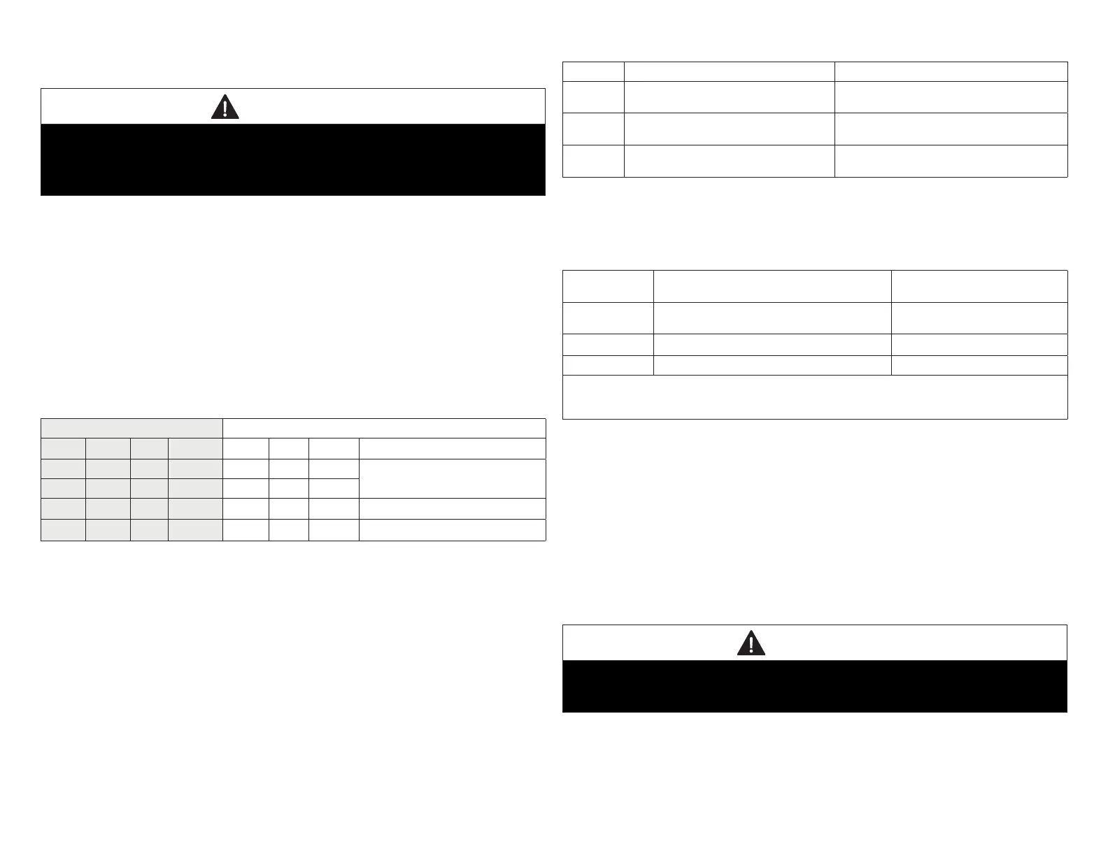
Table 6. Adjusting for Average CFM Example
Required CFM CFMAdjustedtowithinAverage
Zone CFM Avg %CFM Adj Avg %CFM
1 500 713 0.70 600 738 0.81 Damper linked with Zone 2
2 825 1.16 825 1.12
3 775 1.09 775 1.05
4 750 1.05 750 1.02
1.7.2. VariableSpeedBlowerMotor(VSM)
Indoor units with variable speed “blower” motors (VSM) are required to allow
the zone control system to distribute adequate air to each zone. Use only units
recommended in the following 3 options referenced in “1.7.3. Selecting/Installing
Indoor and Outdoor Units” as only those will work with the Harmony III zoning
system; other types of units will not allow the Harmony III zoning system to
proportion the amount of air going to each zone.
1.7.3. Selecting/Installing Indoor and Outdoor Units
Outdoor units may be single or two-stage; use the following table to determine
which to use, based on the number of zones being implemented, and whether the
air conditioned zones are of equal or unequal size.
Table 7. Indoor / Outdoor Options
Options Indoor Unit Outdoor Unit
1
Any Lennox Gas Furnace with VSM
only.
Lennox Air Conditioner unit as described in
“Table 8. Lennox AC or Heat Pump Units”.
2
Lennox Air Handler Unit with VSM
only.
Lennox Heat Pump unit as described in
“Table 8. Lennox AC or Heat Pump Units”.
3
Any Lennox Gas Furnace with VSM
only.
Lennox Heat Pump unit as described in
“Table 8. Lennox AC or Heat Pump Units”.
NOTE: Limited variations to AC units described herein are detailed. Go to “4.1.
Variations on Common AC Unit Applications” on page 39 for further
details.
Table 8. Lennox AC or Heat Pump Units
Number of
Zones
Comparative Zone Sizes
Lennox AC or Heat
Pump Unit
2 Equal
Single or Two-stage and VSM
units
2 *Unequal Two-stage only and VSM units
3 or 4 Equal or Unequal Two-stage only and VSM units
*Equal zones would have very similar total ducting lengths with CFM requirements within 10% of
average CFM per zone. Unequal would have less similar ducting length and greater variances from
average CFM (see “Table 6. Adjusting for Average CFM Example” on page 7 example).
1.8. OptionalDehumidicationAccessories
The Harmony III zoning system may be used in conjunction with a Humiditrol
®
EnhancedDehumidicationAccessory(EDA)andwhichalsorequiresaHumiditrol
®
ZoningAccessory(39W67).Thisdocumentreectsthecontrolwhichisoutttedfor
connection to, and control of, the EDA in a zone control system using the HZA. See
Humiditrol
®
Zoning Accessory Installation Instructions for more information.
1.9. Installing Zone Control Components
1.9.1. Discharge Air Sensor (DAS)
CAUTION
This device is manufactured using unpainted and pre-painted metal. Sharp
sheet metal edges can cause injury. When installing the device, avoid accidental
contact with sharp edges.
Install the discharge air sensor in the discharge plenum downstream from the
cooling coil. Be sure that the discharge air will pass over the sensor before the air
isdistributedintotheductsystem.Typicalup-owsensorapplicationsareshownin
gure4;thesensordimensionsshown(distancefromheatstrips,coil,andposition
in plenum) also apply to other applications.

 Loading...


