40
System configuration jumpers:
HP;
1COOL or 2COOL.
E-Heat stage jumper set on #
agreeing with # of available heat
stages.
E-HEAT Selector Switch always
ON.
As applicable, cut jumpers and
harness wires.
Y1
Y2
C
R
R
G
W1
W2
W3
C
DS
Y1
Y2
Y1
Y2
O
RC
W1-Def
RH
G
W1
W2
W3
DS
Equipment
Equipment
Condensing
Unit
VSM Air
Handler
tric Heat
For any option or variation, connect thermostat wire between “C”
on terminal strip(s) of controlled equipment and zone control
IMPORTANT!
DO NOT MAKE
CONNECTIONS
TO Y1 AND Y2
Figure 28. CoolingwithElectricHeat
4.2. Electrical Adjustments
4.2.1. Communicating Indoor Control
As illustrated in the following diagram, make the following adjustments:
1. Cut on-board link R to DS (Dehum or Harmony).
2. Remove jump bars from W1 to W2 and W2 to W3.
3. DO NOT CUT on-board links Y1-Y2 2 STAGE COMPR and R-O HEAT PUMP.
CUT on board
Link R-DS
Remove
W1-W2 and W2-W3
Jumper Bars from the
terminal strip
DO NOT CUT
on board links
Y1-Y2 2 Stage Compr
and R-0 Heat Pump
Figure 29. Electrical Adjustments for Air Handler Control CBX32MV
(revision 06) and CBX40UHV
4.2.2. Non-Communicating Indoor Control
These air handler blower motors are controlled by the BDC3 drive control; CFM
adjustment Is by jumper setting selection.
Locate the BDC3 board in the blower control box. Before connecting the zone control
panel to the BDC3 board, complete all of the applicable electrical adjustments as
showninthefollowinggure.
NOTE: Before cutting wires or jumpers, be sure your installation is not affected by
“4.1. Variations on Common AC Unit Applications” on page 39.
1
4
7
3
6
9
K20 INDOOR
BLOWER RELAY
JP1
BDC3
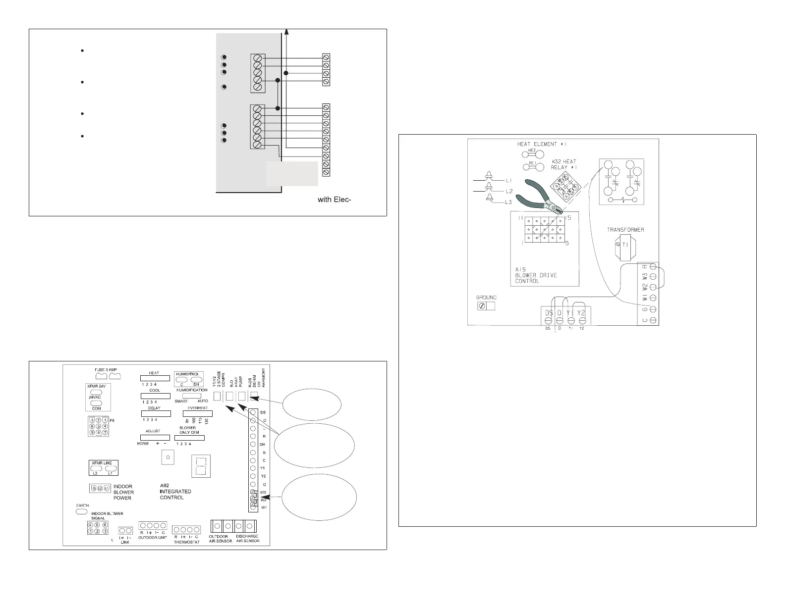
Electrical Adjustments
As shown in this diagram, make the following adjustments:
In all cases except “Cooling Only” or CBWMV units:
Cut wire near the BDC3 board JP1 pin 2
Tape exposed end of short JP1 pin 2 wire
Re-route wire connected to K20 terminal 4; strip end and
connect to terminal “G” (K20 wiring change not required
on CBWMV)
If CBWMV, remove pink wire TB1-W1 to J46-2
DO NOT CUT jumper R - O
DO NOT CUT Jumper Y1 - Y2
In all cases, CUT Jumper DS - Y1
q
q
w
w
e
e
r
Except for cooling onloy units, remove any jumper
between R-W2 and R-W3
r
Figure 30. Electrical Adjustments for Air Handler Control CBX32MV (pre-
rev. 06) and CBWMV

 Loading...


