20
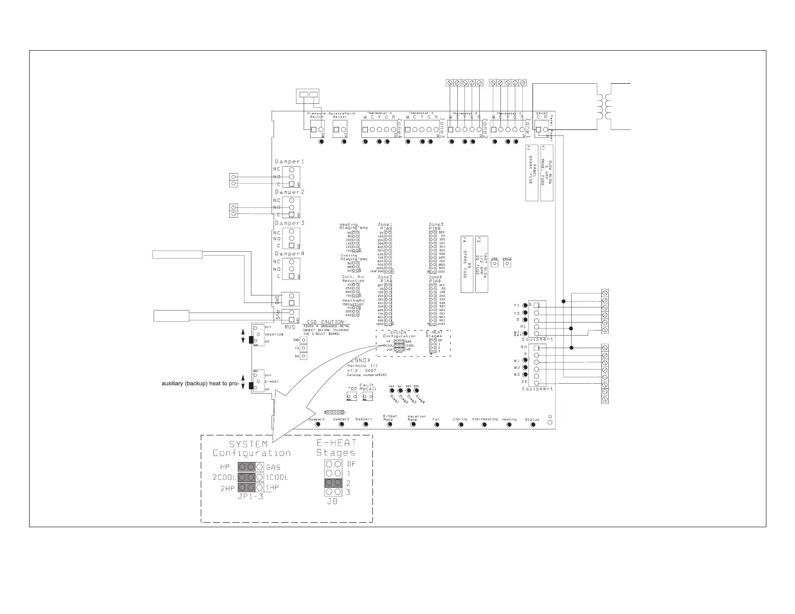
2.2. Variable Speed Motor (VSM) Air Handler and Heat Pump - Option 2 (Zoning System)
IMPORTANT!
DO NOT MAKE
CONNECTIONS
TO Y1 AND Y2
Vacation OFF for individual
zone control.
Vacation ON for all zones to be
conditioned at the same time.
Emergency Heat OFF to allow
Heat Pump to provide heat.
Emergency Heat ON to force
vide all heating (disallows heat
pump from providing any heat).
R
C
Y1
Y2
O
W1
R
G
W1
W2
C
DS
Y1
Y2
DAMPERS
(Spring open, power close)
Thermostat 2Thermostat 1
240
VAC
24
VAC
PRESSURE SWITCH
21J18 (HFC-22)
27W13 (HFC-410A
W C Y G R
W C Y G R
IMPORTANT
VARIABLE
SPEED AIR
HANDLER
HEAT PUMP
System Configuration & E-Heat
jumper settings
CONNECT TO THE
SAME POWER
SUPPLY AS THE AIR
HANDLER
ZONE CONTROL
TRANSFORMER
Connect thermostat gauge
wire to “C” terminal on heat
pump terminal strip.
Connection for remote vacation
switch or Humiditrol Accessory
Discharge Air Sensor
(19V99) is included
NOTE: Select number of HP stages by placing jumper in appropriate position
(2-Stage HP illustrated)
NOTE: Do not wire “Y” wires(s)
from the Harmony III control
panel to the air handler
terminals strip. Doing so will
cause the motor to search
for proper CFM.
Figure 20. Option 2 - Typical Lennox Heat Pump and Lennox Variable-Speed Air Handler (Troubleshooting)

 Loading...


