60
6.1.2. Fault Recall and Time Delay Override
When the Time Delay Override is pressed and held, the internal clock speeds up
by a factor of 60. This overrides the current time delay and permits the next event
tooccur.“Table14.TimeDelays”onpage60identiesthetimedelaysusedby
the system.
When the Fault Recall button is pressed and released (clicked), the fault codes are
displayed (10 most recent). When the fault recall button is pressed and held, the
fault codes are erased. Each code will be displayed for 10 seconds starting with
the most recent code, then the next most recent, and so on. Pressing the button
while recalling fault codes will bypass the 10-second timer and go right to the next
fault code.
Use the Fault Recall button to observe diagnostic codes that will indicate either
correct operation, or help checkout and troubleshoot problems in the zone control
system.“Table15.DiagnosticsCodes”onpage62identiesalldiagnosticcodes.
Press the button once while the system is operating. The system will respond by
momentarily lighting all four DIAG LEDs then displaying the error code, if an error
code is stored in memory. This allows a visual check to verify that all four LEDs are
operational before displaying an error code.
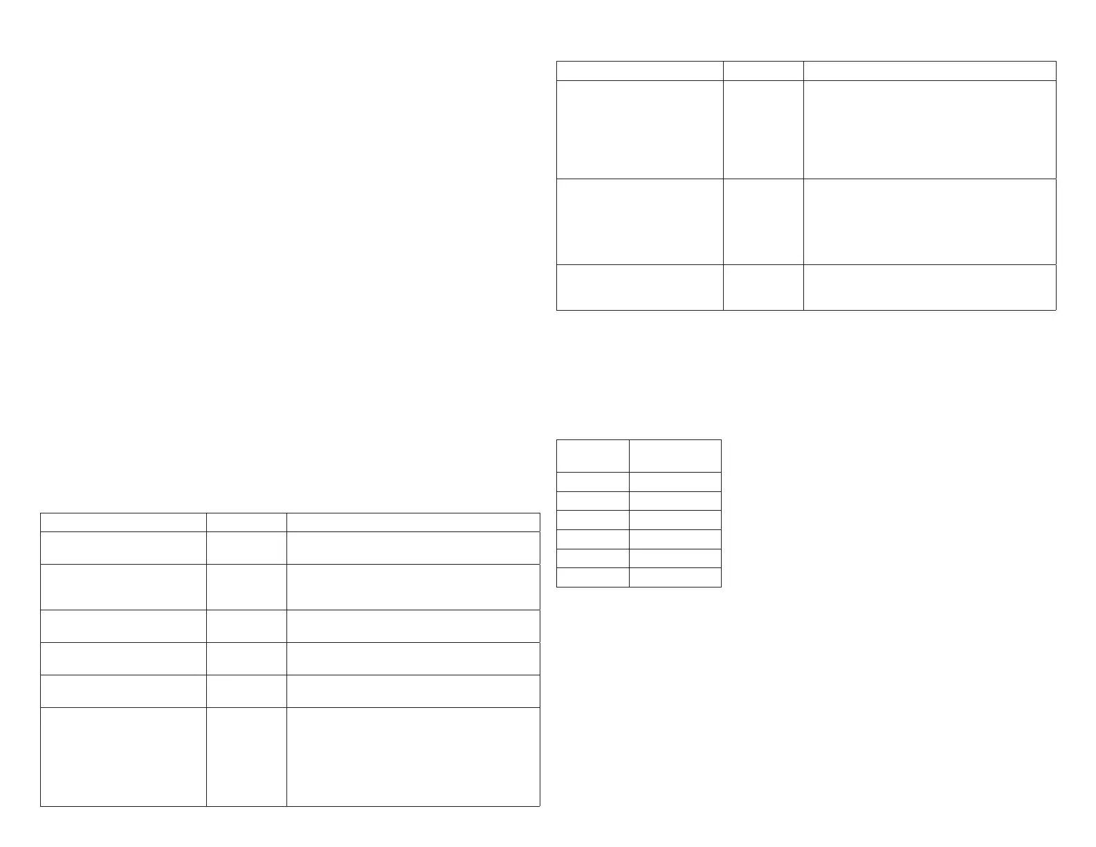
6.1.3. Time Delays
Timers used in the Harmony III zoning system dene delays which precede or
follow a demand, depending on the type of function. The delays are used to control
equipment connected to the system. The following table shows how the most
noticeable delays are used.
Table 14. Time Delays
Delay Time Function
Blower Off Delay (gas heat
only)
3-1/2 min.
Gas Furnace only. Delivers air into last zone
called during cool down following heat demand.
Compressor Speed Change 4 min.
Between low speed and high speed in order
to make sure steady state is reached before
staging.
Compressor Off Time 5 min.
At end of demand. Equalizes pressure in
refrigerant system and prevents short cycling.
Heat Staging (electric) 2 min.
Between staging up or down (May stage faster to
prevent overshoot/undershoot).
Heat Staging (gas) 3 min.
Between staging up or down to achieve steady
state.
Dual Fuel Furnace Lock-in
Timer
3 hrs.
Starts when system enters dual fuel furnace
heating when the outdoor temperature is above
balance point. When operating within this 3-hour
time, only the furnace is used for heating. Heat
pump will be tried again on the next call after this
timer expires. Diagnostic LEDs 2, 3, and 4 will
ashwhenthistimerisactive.
Table 14. Time Delays
Delay Time Function
Damper Hold 3-1/2 min.
Thistimerisdenedastheamountoftime
to hold the last zone calling open past the
thermostat call drop out. During this time, the
panel will not energize the blower (except when
a continuous fan call exists); the controlled
equipment will provide this signal. This is a non-
adjustable timer set at 210 seconds.
Auto-changeover 20 min.
When opposing demands are present, zone
control system must work to satisfy current
demand at least 20 min. If current demand is
notsatisedaftertimehaselapsed,systemwill
changeover and satisfy opposing demand. On
and Off delays above will also apply.
Dual Fuel Auto-changeover 20 min.
When temperature is above balance point, heat
pump will operate for 20 minutes before allowing
gas furnace to take over heating demand.
6.1.4. Discharge Air Probe Checkout (All Systems)
The discharge air sensor is a temperature-dependent resistor; the higher the
temperature, the lower the resistance. To conrm the sensor is functioning,
disconnect both sensor leads from the zone control panel. Using a digital voltmeter
(DVM) set to read resistance, touch the leads from the sensor to the probes of the
DVM.
Temp ºF
(ºC)
Resistance
(ohms)
65 (18) 13476
70 (21) 11884
75 (24) 10501
80 (27) 9298
85 (29) 8249
90 (32) 7333

 Loading...


