39
4. air Handlers
4.1. Variations on Common AC Unit Applications
4.1.1. Heating/Cooling Equipment Installation
Follow all equipment installation instructions provided with each unit.
4.1.2. Air Handler Wiring
Aftertheairhandler unitisinstalled,eldwirethelinevoltageasshowninthe
installation instructions provided with the unit. Use thermostat wire to connect the
air handler to the zone control panel and to connect wire from zone control panel
24V C to air handler terminal strip C (24VAC common) blue wire in CBX25UHV air
handler..
NOTE: Be sure to remove the factory installed jumper bar between W1 to W2
and W2 to W3 (CBA38MV, CBX40 or CBX32MV rev 06) or remove the
jumper wires between R to W1 and R to W2 (CBX32MV prior to rev 06).
CBX25UHV does not have any factory jumpers.
4.1.3. Variations
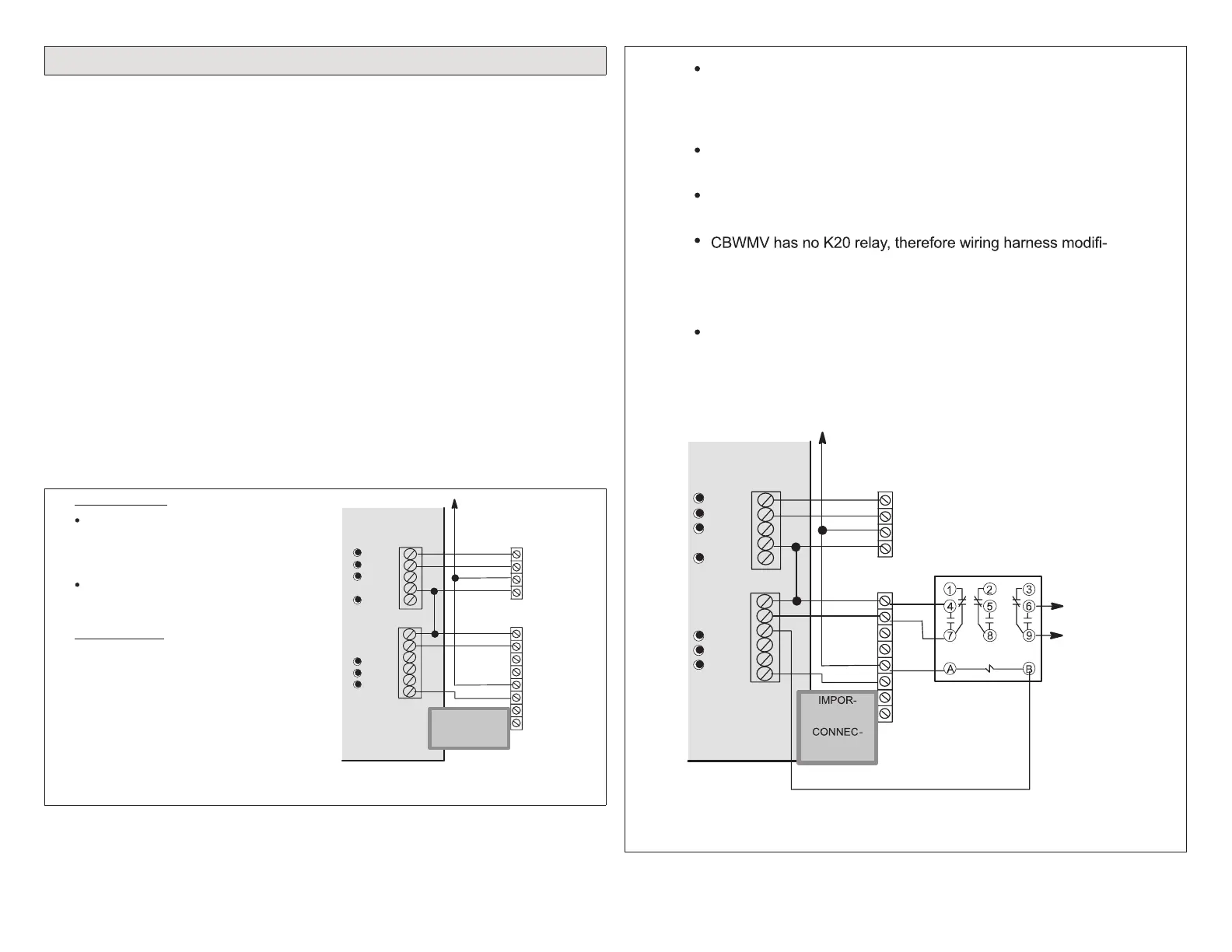
Severalvariationsmayberequiredforspecicapplications.Thefollowinggure
shows alternate wiring and describes specic jumper congurations and other
specialmodicationsrequiredforeachvariation.
For any option or variation, connect thermostat wire between “C”
on terminal strip(s) of controlled equipment and zone control
COOLING ONLY
System configuration jumpers:
GAS;
1COOL or 2COOL;
Others do not matter.
As applicable, cut jumpers and harness
wires
HEATING ONLY
NOTE - JUMPER between RC and RH
must be in place on the control!
Y1
Y2
C
R
R
G
W1
W2
C
DS
Y1
Y2
Y1
Y2
O
RC
W1-Def
RH
G
W1
W2
W3
DS
Equipment
Equipment
Condensing
Unit
VSM Ai
Handler
IMPORTANT!
DO NOT MAKE
CONNECTIONS
TO Y1 AND Y2
Figure 26. Cooling Only
For any option or variation, connect thermostat wire between “C”
on terminal strip(s) of controlled equipment and zone control
Y1
Y2
C
R
R
G
W1
W2
C
DS
Y1
Y2
System configuration jumpers:
GAS;
1COOL or 2COOL;
Others do not matter.
AHC (prior to revision 06): Cut or remove 24 volt jumper Y1
to DS.
AHC (revision 06): Cut R to DS clippable link on air handler
control.
cation is not required.
- Cut or remove 24v jumper Jumper Y1 to DS
- Remove Pink wire from TB1-W1 to J46-2 on CBWMV
CBX25UHV does not have factory jumper between R to DS.
NOTE - K212 field hookup relay must be field provided on the
CBX25UHV, CBX32MV and CBX40UHV
NOTE - DAS must be located downstream of the cooling coil and
HW coil
Y1
Y2
O
RC
W1-Def
RH
G
W1
W2
W3
DS
Equipment
Equipment
Condensing
Unit
CBX25UHV, CBWMV,
CBX32MV OR
CBX40UHV USED
WITH HOT WATER
COIL
TO
BOILER
OR
ZONE
CONTROL
K212 (CAT#
67K66) FIELD
HOOKUP
RELAY MUST
BE PROVIDED
ON CBX25UHV,
CBX32MV OR
CBX40
VSM
Air
Handler
TANT! DO
NOT MAKE
TIONS TO
Y1 AND Y2
Figure 27. Hot Water Coil and Current Lennox Air Handlers

 Loading...


