46
4.2.3.3. CoolingOnlyorCoolingwithHotWaterCoil(Non-HeatPump)
Job Name:
Indoor Unit Model:
Outdoor Unit Model:
CBX32MV, Rev 6 or higher, CBX40UHV and CBA38MV Indoor Unit Setup:
9 Cut on-board link R to DS “DEHUM or HARMONY”
9 For Hot Water Coil Only—Add K212 Relay and wire per Harmony III wiring detail. NOTE -
Discharge air sensor must be located downstream of cooling coil and hot water coil.
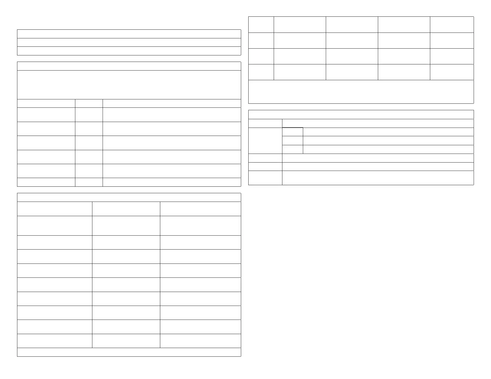
9 Air handler control jumper settings:
Function Settings Condition
COOL
This setting, along w/ ADJUST setting, determines maximum
system CFM (See blower tables)
ADJUST
Setting affects both heating and cooling blower speeds (see
blower tables to determine setting)
HEAT HIGH
Heating blower speed selection – Ignored by Harmony III
zoning system
DELAY 4
Cooling blower ramping – Ignored by Harmony III zoning
system
BLOWER ONLY CFM
Continuous fan speed – Ignored by Harmony III zoning
system
EVENHEAT EVENHEAT is not used with Harmony III zoning system
Panel Setup:
9 Heating staging jumper Circle one: 85 90 100 110
120 130
Recommended 120 deg-F
9 Zone 1 PIAB 140F DAS
jumper in place
Circle one: Yes No See “1.10.4. Zone 1 PIAB
Jumpers – 140ºF DAS” on page
10.
9 Cooling staging jumper Circle one: 50 55 60 Select desired discharge air temp
during cooling
9 Cont. Air Reduction jumper Circle one: 0 25 50 75 Percentageairowreductionfor
continuous fan operation
9 Heating Air Reduction
jumper
Circle one: 0 20 40 Percentageairowreductionfor
heating mode
9 SystemConguration
jumpers
Circle one: HP GAS Set to GAS
9 Stages Circle one: 2COOL
1COOL
Set to match condenser, 1 or 2
stage
9 Stages Circle one: 2HP 1HP Ignored for gas heat, non-heat
pump application
9 E-HEAT Stages Circle one: DF 1 2 3 Ignored for gas heat, non-heat
pump application
9 Desired total system CFM
with all zones calling:
Total system CFM per
tables:
Minimum CFM:
9 CB unit “minimum” CFM ____________ (determined by unit spec listed below unit blower table)
√Zone1 Name: Desired CFM: PIAB Setting: Actual CFM:
√Zone2 Name: Desired CFM: PIAB Setting: Actual CFM:
√Zone3 Name: Desired CFM: PIAB Setting: Actual CFM:
√Zone4 Name: Desired CFM: PIAB Setting: Actual CFM:
NOTE: All of the above are recommended starting positions for DIP switches and
Harmony III zoning system jumpers. Slight variations may be required
during system start up and operation checks.
Field Wiring Checklist
√ Indoor Unit Wiring Completed:
DS on Harmony III to DS on indoor unit connected
C on indoor unit connected to Harmony III transformer C
No connection to Y1 or Y2 on indoor unit.
√ Outdoor Unit Wiring Completed
√ Thermostat and Damper Wiring Completed
√ Discharge Sensor wired to Harmony III zoning system and if a hot water coil is used,
the sensor must be located down stream of the hot water coil.

 Loading...


