3. Gas Furnace
3.1. Typical Wiring for Variable-Speed Gas Furnace and Outdoor AC Unit - Option 1
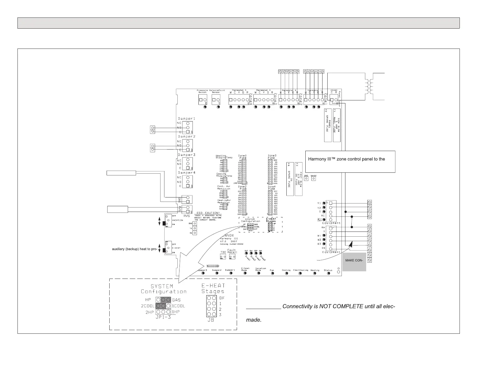
IMPORTANT!
DO NOT
NECTIONS
TO Y1 AND
Y2
Vacation OFF for individual
zone control.
Vacation ON for all zones to be
conditioned at the same time.
Emergency Heat OFF to allow
Heat Pump to provide heat.
Emergency Heat ON to force
vide all heating (disallows heat
pump from providing any heat).
Y1
Y2
C
R
R
G
W1
W2
C
DS
Y1
Y2
DAMPERS
(Spring open,
power close)
120
VAC
24
VAC
IMPORTANT!
trical adjustments (jumpers and wiring changes) have been
IMPORTANT
Connect
thermostat‐gauge
wire to integrated
control “C” terminal
Thermostat 2 Thermostat 1
W C Y G RW C Y G R
Variable
Speed
Furnace
2‐Stage Condensing
Unit shown (No Y2
wire on 1-Stage Unit)
NOTE - Do not wire “Y” wire(s) from the
furnace terminal strip. Doing so causes the
motor to “search” for proper CFM.
ON G71MPP &
SLP98 Furnace -
W2 Not required,
but may be
connected to
increase firing rate.
CONNECT TO
THE SAME
POWER
SUPPLY AS
THE GAS
FURNACE
SEE IMPORTANT
NOTE BELOW!
NOTE:
SELECT # OF
COOL STAGES
BY PLACING
JUMPER IN
APPROPRIATE
POSITION.
(2-STG CLG
SHOWN)
ZONE CONTROL
TRANSFORMER
Discharge Air Sensor (19V99)
Included
Connections for remote
vacation switch or
Humiditrol zoning
accessory
Figure 22. Harmony III zoning system Option 1 - Typical Lennox Variable-Speed Gas Furnace and 1- or 2-Stage Air Conditioner

 Loading...


