59
6. trOublesHOOtinG
6.1. Operation and Troubleshooting Indicators
6.1.1. Zone Control Panel LEDs
The zone control system operation is indicated by light emitting diodes (LEDs)
located on the zone control panel. In addition to operating condition, the LEDs
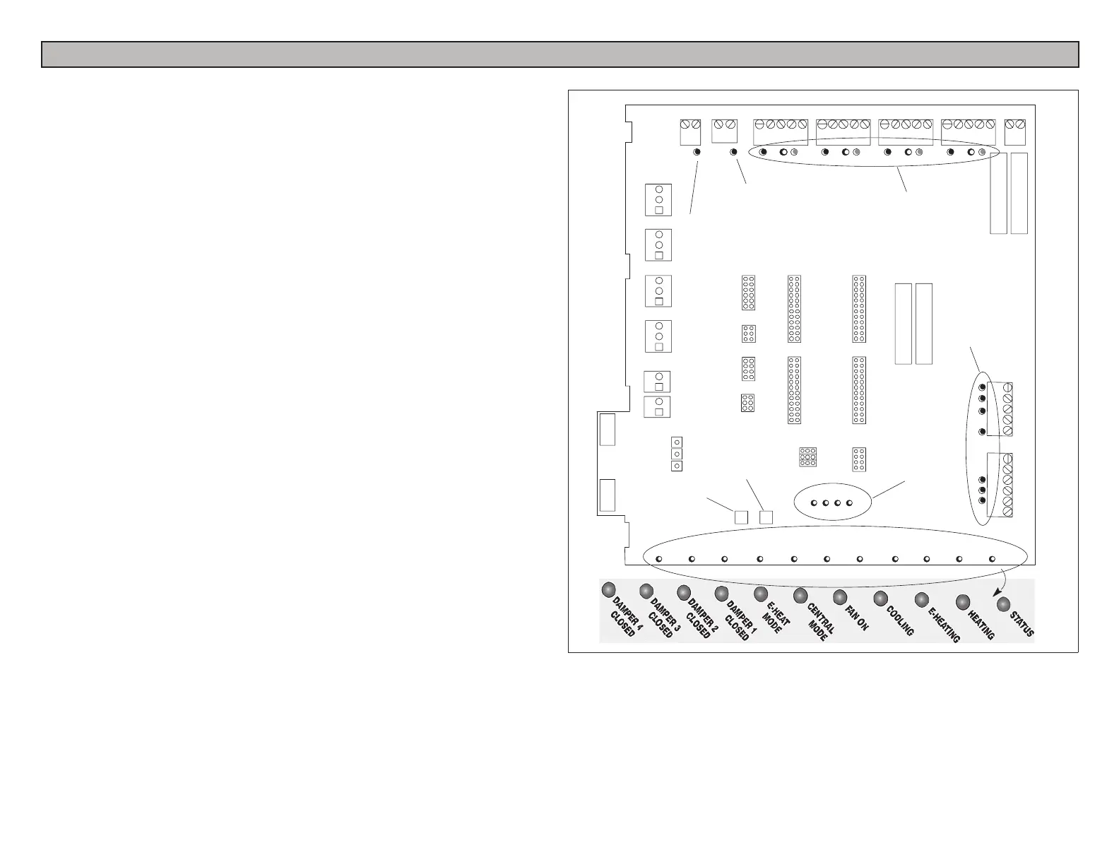
providevaluableinformationsystemtroubleshooting.TheLEDs(showningure
30) are thermostat, diagnostic, and output status.
1. Thermostat LEDs — Located along the upper edge of the zone control panel.
Each zone has three LEDs to indicate a call for heating or cooling: green
(indicates a Y / compressor demand), red (indicates a W / heating demand)
and amber (indicates a G / indoor blower demand). These LEDs are labeled
according to the zone and demand.
2. Diagnostic LEDs — Diags 1, 2, 3, 4—located near the bottom center of the
the zone control panel. These LEDs aid the technician in troubleshooting
problems. When an error is detected, LEDs illuminate in a pattern. See Fault
Recall and Time Delay Override on page 58.
3. Output LEDs — Located along the bottom of the zone control panel and
near connection terminals. These red LEDs indicate the output status of
dampers, furnace, outdoor unit, etc. When an output is powered or active, the
corresponding LED is illuminated.
4. PressureSwitchLED — Located at the top left corner. Green LED illuminates
when the heat pump pressure switch is closed indicated normal pressures. The
LED will be off when the pressure switch opens under abnormal or excessive
condensing pressure in the heat pump heating mode. Pressure switch is used
only on heat pump systems.
5. Balance Point Sensor LED — Located at the top left corner. Red LED
illuminates when the balance point sensor is closed indicating outdoor
temperature is below the balance point sensor setting. Only used on dual fuel
heat pump systems.
The LEDs are labeled according to output and function. For example, if Damper
1 LED is illuminated, it’s damper has been signaled to close; when the LED is
extinguished,it’sdamperhasbeensignaledtoopen,allowingairowtothatzone.
THERMOSTAT
LEDs
OUTPUT STATUS LEDs
DIAGNOSTIC
LEDs
TIME DELAY
OVERRIDE
FAULT
RECALL
EQUIPMENT
OUTPUT LEDs
OUTDOOR THERMOSTAT /
BALANCE POINT LED
PRESSURE
SWITCH LED
Figure 35. System Indicators/Troubleshooting Devices

 Loading...


