47
Job Name:
Indoor Unit Model:
Outdoor Unit Model:
CBX25UHV (all units) and CBX32MV units prior to Revision 06 Indoor Unit Setup:
9 Remove DS to Y1 jumper”
9 No jumper between DS and Y1 on CBX25UHV
9 On the CBX32MV the wire from K20 terminal 4 to BDC3 board JP1 pin 2 must be re-routed to
establish an electrical connection between K20 terminal 4 and terminal G. Cut the wire near
JP1 pin 2.
9 Using the wire still connected to K20 terminal 4, strip the cut end and connect it to terminal G.
Tape the exposed end of the short JP1 pin 2 wire.
9 On the CBX25UHV the blue wire that goes between plug # 2 of the circuit board and one side
of the contacts on the BR relay must be removed and connected to the G pigtail. Tape off end of
wire going to the circuit board jack plug.
9 Remove any factory-installed jumpers between terminal R and W1, W2, or W3. No jumper
between R and W1 or W2 on CBX25UHV.
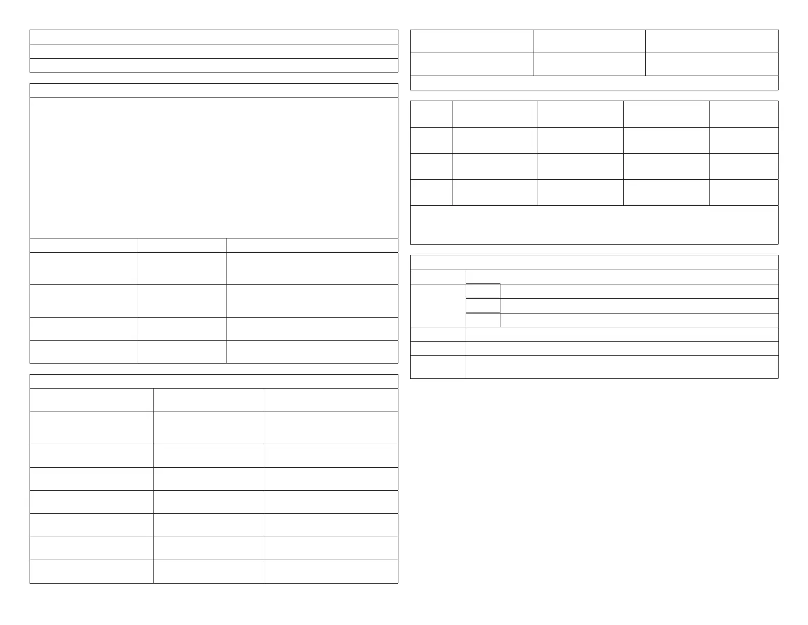
9 BDC3 control clip jumper settings (CBX25UHV and CBX32MV
Function Settings Condition
COOL
This setting, along with ADJUST setting,
determines maximum system CFM (see
blower tables)
ADJUST
Setting affects both heating and cooling
blower speeds (see blower tables to
determine setting)
HEAT 4
Heating blower speed selection – Ignored by
Harmony III zoning system
DELAY 4
Cooling blower ramping – Ignored by
Harmony III zoning system
Panel Setup:
9 Heating staging jumper Circle one: 85 90 100 110
120 130
Recommended 120 deg-F
9 Zone 1 PIAB 140F DAS
jumper in place
Circle one: Yes No See “1.10.4. Zone 1 PIAB
Jumpers – 140ºF DAS” on page
10.
9 Cooling staging jumper Circle one: 50 55 60 Select desired discharge air temp
during cooling
9 Cont. Air Reduction jumper Circle one: 0 25 50 75 Percentageairowreductionfor
continuous fan operation
9 Heating Air Reduction
jumper
Circle one: 0 20 40 Percentageairowreductionfor
heating mode
9 SystemConguration
jumpers
Circle one: HP GAS Set to GAS
9 Stages Circle one: 2COOL
1COOL
Set to match condenser, 1 or 2
stage
9 Stages Circle one: 2HP 1HP Ignored for gas heat, non-heat
pump application
9 E-HEAT Stages Circle one: DF 1 2 3 Ignored for gas heat, non-heat
pump application
9 Desired total system CFM
with all zones calling:
Total system CFM per
tables:
Minimum CFM:
9 CB unit “minimum” CFM ____________ (determined by unit spec listed below unit blower table)
√Zone1 Name: Desired CFM: PIAB Setting: Actual CFM:
√Zone2 Name: Desired CFM: PIAB Setting: Actual CFM:
√Zone3 Name: Desired CFM: PIAB Setting: Actual CFM:
√Zone4 Name: Desired CFM: PIAB Setting: Actual CFM:
NOTE: All of the above are recommended starting positions for DIP switches and
Harmony III zoning system jumpers. Slight variations may be required
during system start up and operation checks.
Field Wiring Checklist
√ Indoor Unit Wiring Completed:
DS on Harmony III to DS on indoor unit connected
C on indoor unit connected to Harmony III transformer C
No connection to Y1 or Y2 on indoor unit.
√ Outdoor Unit Wiring Completed
√ Thermostat and Damper Wiring Completed
√ Discharge Sensor wired to Harmony III zoning system and if a hot water coil is used,
the sensor must be located down stream of the hot water coil.

 Loading...


