37
Do dampers respond to demand? 0
volts AC = open. 24 volts AC =
closed. Dampers should drive closed
when 24 volts is jumpered to damper
motor.
Is wiring correct & in good condition?
Are thermostats wired correctly?
Does zone control system respond appropriately to demand?
Heat/cool thermostat used? (Must not use heat pump thermostat.)
Does electronic thermostat have relay switching output? If not, isolation relays may need to be used.
24VAC supplied to each thermostat terminal R from zone control system?
Check each thermostat for output signal when calling. Heating output? Cooling output?
“C” connected
to “C”?
Fuses OK?
Error code present? If
so, see troubleshooting/
diagnostic section of this
manual
rectly for furnace and
cooling?
Is discharge
probe installed?
Is probe located
in discharge air
rectly?
Does outdoor unit respond to
demand?
Is it operating properly?
gized in response to demand?
ergize appropriate outputs?
ing?
er to R?
puts?
Does blower speed change as
zone demand changes? If no,
does DS output vary from 0 to
25VDC?
Line Voltage to transformer?
24VAC from transformer to zone control panel?
Are all wire connections good? Are all wire connections correct?
(No pressure Switch should be installed.)
DAMPERS
120
VAC
24
VAC
Thermostat 2Thermostat 1
W C Y G R
DISCHARGE
AIR SENSOR
THERMOSTATS
Y1
Y2
C
R
R
G
W1
W2
C
DS
Y1
Y2
Are PIAB jumpers set correctly?
Only 1 jumper per Zone? (Zone Control
System Jumper Settings
(NOTE: Zone 1 may have a second
jumper on 140F DAS pins)
Has 140F DAS jumper been installed (if
required)
duction jumpers set correctly?
Do jumpers provide appropriate
speed reduction? If no, check
indoor unit before replacing
zone control panel.
Have heating and cooling
staging jumpers been set for
desired 2nd stage operation?
140F DAS
jumper
W C Y G R
HUMIDITROL ZONING
ACCESSORY CONTROL
ZONE PANEL TRANSFORMER
TO FURNACE
POWER SUPPLY
H
M
CC
WR
GAS VALVE
BROWN
ORANGE
12B
IFC
IFC
9B
YELLOW
CONNECT HARMONY III W2 DIRECTLY TO
THE HIGH STAGE TERMINAL ON GAS VALVE
(EXCEPT -030 MODEL)
H
M
CC
WR
GAS VALVE
BROWN
ORANGE
12B
IFC
IFC
9B
YELLOW
FACTORY WIRING
MODIFIED WIRING
2-STAGE
OUTDOOR
CONTROL
VARIABLE
SPEED
FURNACE
CONTROL
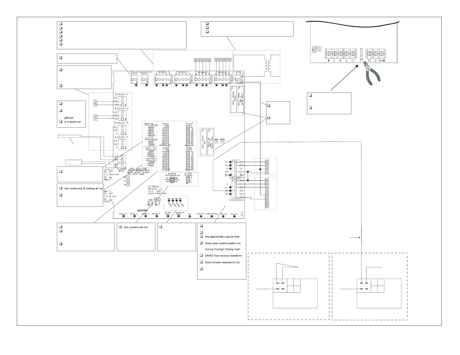
Verify that Furnace
control dehumid
link it cut.
Verify that NO connections
are made to Y1 or Y2.
DEHUM
HEAT
PUMP
2STAGE
COMP
CUT DEHUM LINK
VARIABLE SPEED FURNACE CONTROL
Figure 25. IntegratedControlCableModicationsforFurnaces-ML180UHVModelsOnly

 Loading...


