43
Job Name:
Indoor Unit Model:
Outdoor Unit Model:
CBX25UHV (all units) and CBX32MV units prior to Revision 06 Indoor Unit Setup:
9 Remove DS to Y1 jumper”
9 No jumper between DS and Y1 on CBX25UHV
9 On the CBX32MV the wire from K20 terminal 4 to BDC3 board JP1 pin 2 must be re-routed to
establish an electrical connection between K20 terminal 4 and terminal G. Cut the wire near
JP1 pin 2.
9 Using the wire still connected to K20 terminal 4, strip the cut end and connect it to terminal G.
Tape the exposed end of the short JP1pin 2 wire.
9 On the CBX25UHV the blue wire that goes between plug # 2 of the circuit board and one side
of the contacts on the BR relay must be removed and connected to the G pigtail. Tape off end of
wire going to the circuit board jack plug.
9 Remove any factory-installed jumpers between terminal R and W1, W2, or W3. No jumper
between R and W1 or W2 on CBX25UHV.
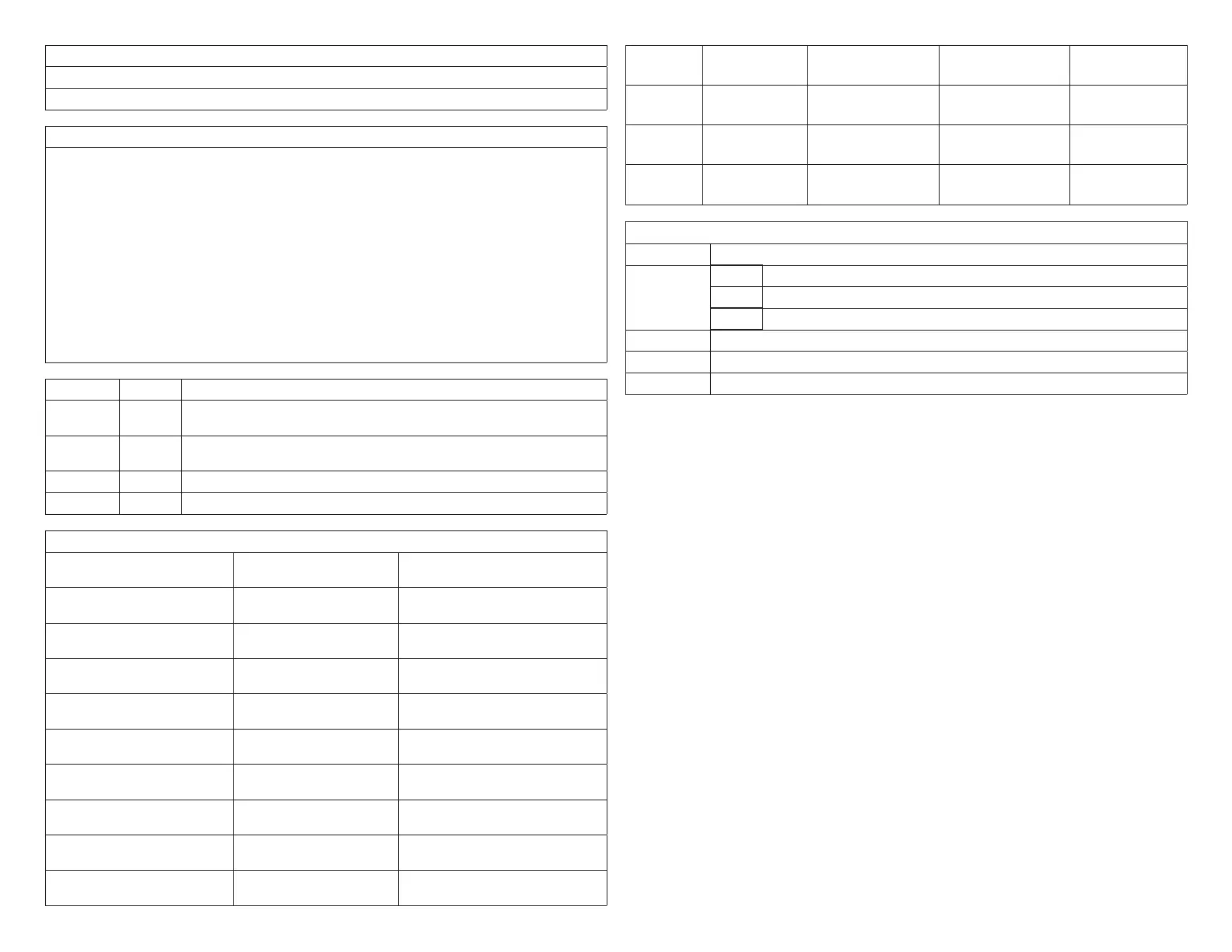
9 BDC3 control clip jumper settings (CBX25UHV and CBX32MV):
Function Settings Condition
COOL
This setting, along w/ ADJUST setting, determines maximum system CFM
(See blower tables)
ADJUST
Setting affects both heating and cooling blower speeds (see blower tables
to determine setting)
HEAT HIGH Heating blower speed selection – Ignored by Harmony III zoning system
DELAY 4 Cooling blower ramping – Ignored by Harmony III zoning system
Panel Setup:
9 Heating staging jumper Circle one: 85 90 100
110 120 130
Recommended 120 deg-F
9 Zone 1 PIAB 140F DAS
jumper in place
Circle one: Yes No See “1.10.4. Zone 1 PIAB Jumpers
– 140ºF DAS” on page 10.
9 Cooling staging jumper Circle one: 50 55 60 Select desired discharge air temp
during cooling
9 Cont. Air Reduction jumper Circle one: 0 25 50 75 Percentageairowreductionfor
continuous fan operation
9 Heating Air Reduction
jumper
Circle one: 0 20 40 Percentageairowreductionfor
heating mode
9 SystemConguration
jumpers
Circle one: HP GAS Set to GAS
9 Stages Circle one: 2COOL
1COOL
Set to match condenser, 1 or 2
stage
9 Stages Circle one: 2HP 1HP Ignored for gas heat, non-heat
pump application
9 E-HEAT Stages Circle one: DF 1 2 3 Ignored for gas heat, non-heat
pump application
9 Desired total system CFM
with all zones calling:
Total system CFM per
tables:
Minimum CFM:
9 Zone 1 Name: Desired CFM: PIAB Setting: Actual CFM:
9 Zone 2 Name: Desired CFM: PIAB Setting: Actual CFM:
9 Zone 3 Name: Desired CFM: PIAB Setting: Actual CFM:
9 Zone 4 Name: Desired CFM: PIAB Setting: Actual CFM:
Field Wiring Checklist
√ Indoor Unit Wiring Completed:
DS on Harmony III to DS on indoor unit connected
C on indoor unit connected to Harmony III transformer C,
No connection to Y1 or Y2 on indoor unit.
√ Outdoor Unit Wiring Completed
√ Thermostat and Damper Wiring Completed
√ Discharge Sensor wired to Harmony III zoning system

 Loading...


