Safety engineering
Basic Safety − STO
Electrical installation
10
l
138
EDS700ACBA EN 5.1
10.6.3 Electrical installation
X1 Labelling Description
SIA Safe input, channel A
On double axis devices, there are
two of these connections. For
the assignment to the axes, the
designations "A" / "B" are used.
Independently of this, the
two−channel safe input is always
provided with the channels A
and B.
GS Reference potential GND
SIB Safe input, channel B
i700P00x
Terminal data
Conductor cross−section Tightening torque
!
[mm
2
] [AWG] [Nm] [lb−in]
flexible 0.2 ... 2.5 24 ... 12 − − 3.5 x 0.6
Rigid 0.2 ... 2.5 24 ... 12 − − 3.5 x 0.6
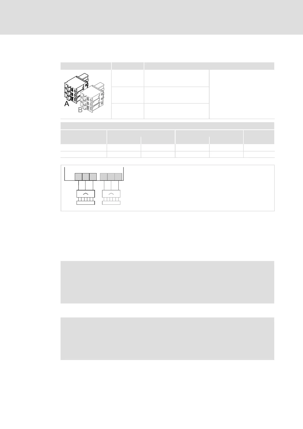
SIBGSSIA
B
SIBGSSIA
A
X1
i700M00x
Fig. 14 Wiring of X1
X1 Connection of integrated safety system
A 1−axis module
B Additionally for 2−axis module
SIA Safety system input, channel A
SIB Safety system input, channel B
GS Reference potential GND
) Note!
To avoid interchanging of the plug−in terminals − especially in the case of
double axis devices −, the plug−in terminals can be provided with coding pins.
Alternatively, we recommend to label the terminals clearly in order to enable
the correct assignment of plugs and sockets.
) Note!
If integrated safety is not to be used for an axis, the safe inputs SIA and SIB of
the axis must be fixedly assigned with "HIGH" potential (24 V).
The wiring should not give the impression of connected safety sensors, or
should be provided with adequate labelling.
 Loading...