Installation
4-21
BA9300SU EN 2.1
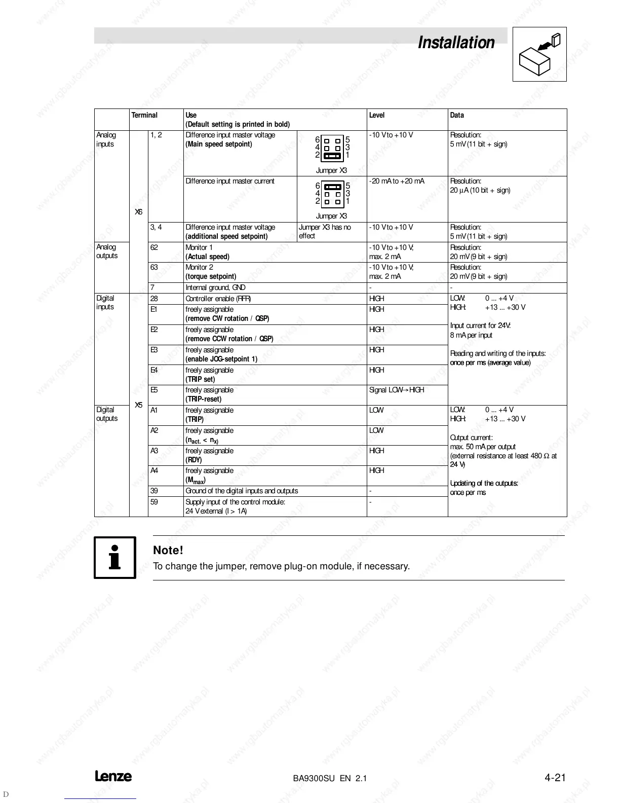
Terminal Use
(Default setting is printed in bold)
Level Data
Analog
inputs
1, 2 Difference input master voltage
(Main speed setpoint)
6
4
2
5
3
1
-10Vto+10V Resolution:
5 mV (11 bit + sign)
Jumper X3
Difference input master current
6
4
2
5
3
1
-20 mA to +20 mA Resolution:
20
µA (10 bit + sign)
X6
Jumper X3
3, 4 Difference input master voltage
(additional speed setpoint)
Jumper X3 has no
effect
-10Vto+10V Resolution:
5 mV (11 bit + sign)
Analog
outputs
62 Monitor 1
(Actual speed)
-10Vto+10V;
max. 2 mA
Resolution:
20 mV (9 bit + sign)
63 Monitor 2
(torque setpoint)
-10Vto+10V;
max. 2 mA
Resolution:
20 mV (9 bit + sign)
7 Internal ground, GND - -
Digital
28 Controller enable (RFR) HIGH
LOW: 0 ... +4 V
inputs
E1 freely assignable
(remove CW rotation / QSP)
HIGH
HIGH: + 13 ... + 30 V
E2 freely assignable
(remove CCW rotation / QSP)
HIGH
Input current for 24V:
8 mA per input
E3 freely assignable
(enable JOG-setpoint 1)
HIGH
Reading and writing of the inputs:
E4 freely assignable
(TRIP set)
HIGH
E5 freely assignable
(TRIP-reset)
Signal LOW
@
HIGH
Digital
outputs
5
A1 freely assignable
(TRIP)
LOW
LOW: 0 ... +4 V
HIGH: + 13 ... + 30 V
A2 freely assignable
(n
act.
<n
x)
LOW
Output current:
A3 freely assignable
(RDY)
HIGH
max. 50 mA per output
(external resistance at least 480
Ω at
A4 freely assignable
(M
max
)
HIGH
39 Ground of the digital inputs and outputs -
ms
59 Supply input of the control module:
24 V external (I > 1A)
-
Note!
To change the jumper, remove plug-on module, if necessary.
 Loading...

