EasyManua.ls Logo

Lenze EVS9322EP User Manual

Lenze EVS9322EP
334 pages
To Next Page IconTo Next Page
To Previous Page IconTo Previous Page
Page #275 background imageLoading...
Page #275 background image
Function library
Function blocks
3.5.56 Ramp function generator (RFG)
3−247
l
EDSVS9332P−EXT DE 2.0
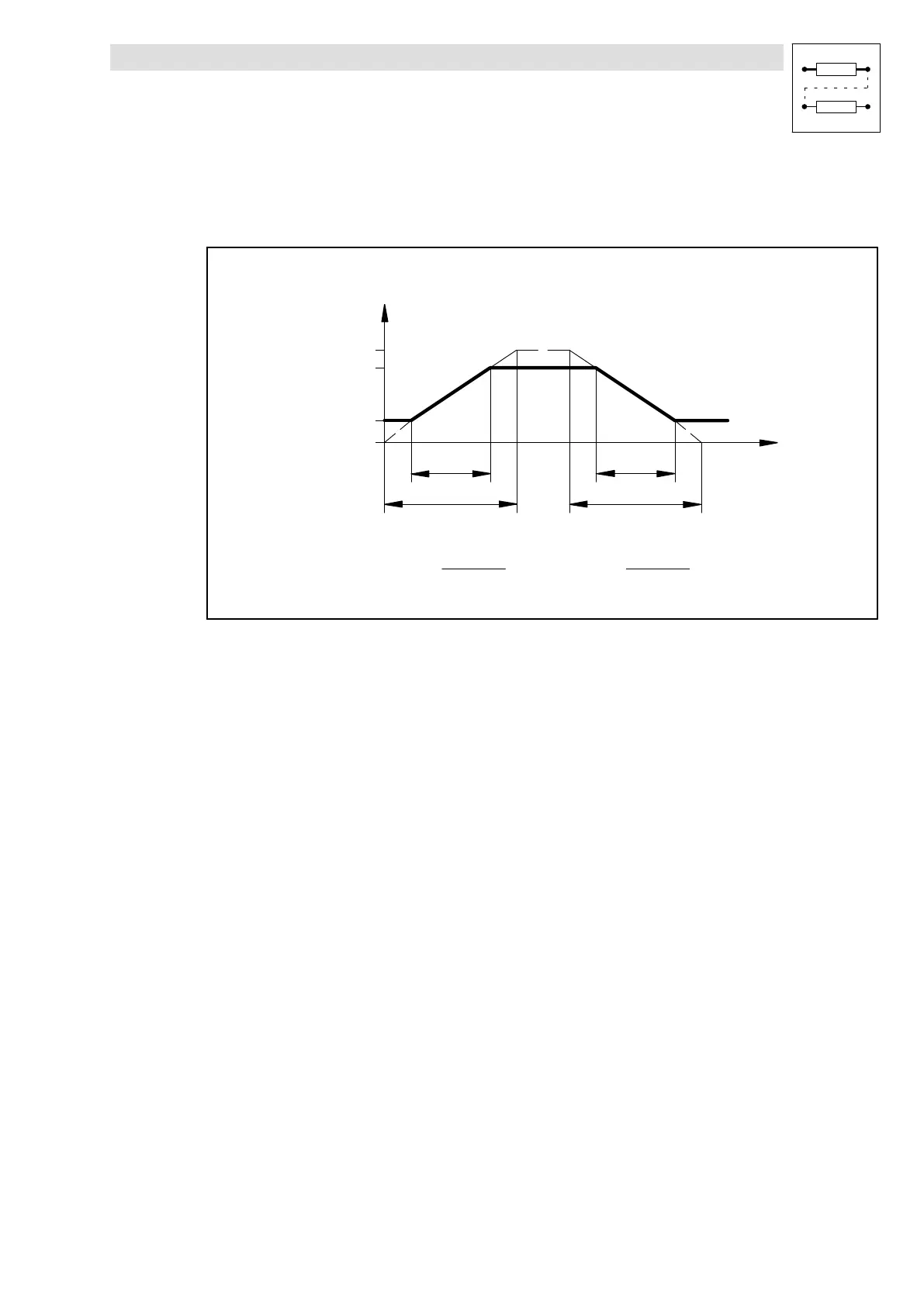
3.5.56.1 Calculation and setting of the times T
ir
and T
if
The acceleration time and deceleration time refer to a change of the output value from 0 to 100 %.
The times T
ir
and T
if
to be set can be calculated as follows:
100 %
0
t
ir
t
if
T
ir
T
if
t
RFG1OUT
[%]
w1
w2
T
ir
+ t
ir
100%
w2 * w1
T
if
+ t
if
100%
w2 * w1
Fig. 3−195 Acceleration and deceleration times of the ramp function generator
t
ir
and t
if
are the times desired for the change between w
1
and w
2
.The values for T
ir
and T
if
can be
set under C0671 and C0672.
3.5.56.2 Loading of the ramp function generator
The ramp function generator can be initialised with defined values via the inputs RFG1−SET and
RFG1−LOAD.
l As long as the input RFG1−LOAD = HIGH, the input RFG1−SET is switched to the output.
l If the input RFG1−LOAD = LOW, the ramp function generator accelerates/decelerates from this
value to its input value within the set T
i
times.

Table of Contents

Question and Answer IconNeed help?

Do you have a question about the Lenze EVS9322EP and is the answer not in the manual?

Lenze EVS9322EP Specifications

General IconGeneral
BrandLenze
ModelEVS9322EP
CategoryController
LanguageEnglish

Summary

2 Configuration

2.1 Configuration with Global Drive Control

Setting up the system using the Global Drive Control software.

2.2 Basic configurations

Overview and selection of predefined basic configurations for the drive.

3 Function library

3.4 Positioning control (POS)

Detailed guide on the positioning control functionality and its parameters.

3.5 Function blocks

Description of various function blocks available for system configuration.

3.4 Positioning control (POS)

3.4.8 Homing

Procedures and settings for homing the drive to establish a reference point.

3.4.8 Homing

3.4.9 Travel profile generator and setpoints

3.4.10 Manual operation

3.4.10.1 Manual positioning

Procedures for manual control of the drive's position.

3.4.11 Program operation

3.4.11.1 Program control

Managing and controlling program execution via external sources.

3.4.13 Program sets (PS)

3.5 Function blocks

3.5.13 Holding brake (BRK)

Danger!

Critical safety warning regarding the BRK function block.

3.5.26 Drive control (DCTRL)

3.5.28 Digital frequency output (DFOUT)

3.5.29 Digital frequency ramp function generator (DFRFG)

3.5.43 Internal motor control (MCTRL)

Purpose

Function of the MCTRL block for controlling drive machine components.

3.5.44 Motor phase failure detection (MLP)

3.5.48 Speed setpoint conditioning (NSET)

3.5.51 Process controller (PCTRL1)

3.5.59 Switching points (SP)

3.5.62 Multi−axis synchronisation (SYNC1)

4 Application examples

4.1 Example 1: Dosing system

Detailed example of a dosing system application.

4.2 Example 2: Spray nozzle control

4.3 Example 3: Path control

Related product manuals