Informaon on pr
oject planning
Project planning process
Overcurrent operaon
The inverters can be driven at higher amperages beyond the rated current if the duraon of
this overcurrent operaon is me limited.
Two ulisaon cycles of 15 s and 180 s are dened. Within these ulisaon cycles, an
overcurrent is possible for a certain me if aerwards an accordingly long recovery phase
takes place.
Cycle 15 s
During this operaon, the inverter may be loaded for 3 s with up to 200 % of the rated current
if aerwards a recovery me of 12 s with max. 75 % of the rated current is observed. A cycle
corresponds to 15 s.
Cycle 180 s
During this operaon, the inverter may be loaded for 60 s with up to 150 % of the rated
current if aerwards a recovery me of 120 s with max. 75 % of the rated current is observed.
A cycle corresponds to 180 s.
The monitoring of the device ulizaon (Ixt) triggers an error if the ulizaon value exceeds a
threshold of 100 %.
The maximum output currents correspond to the switching frequencies and the
o
verload behaviour of the inverters are given in the rated data.
In case of rotang frequencies < 10 Hz, the me-related overload behaviour
may be reduced.
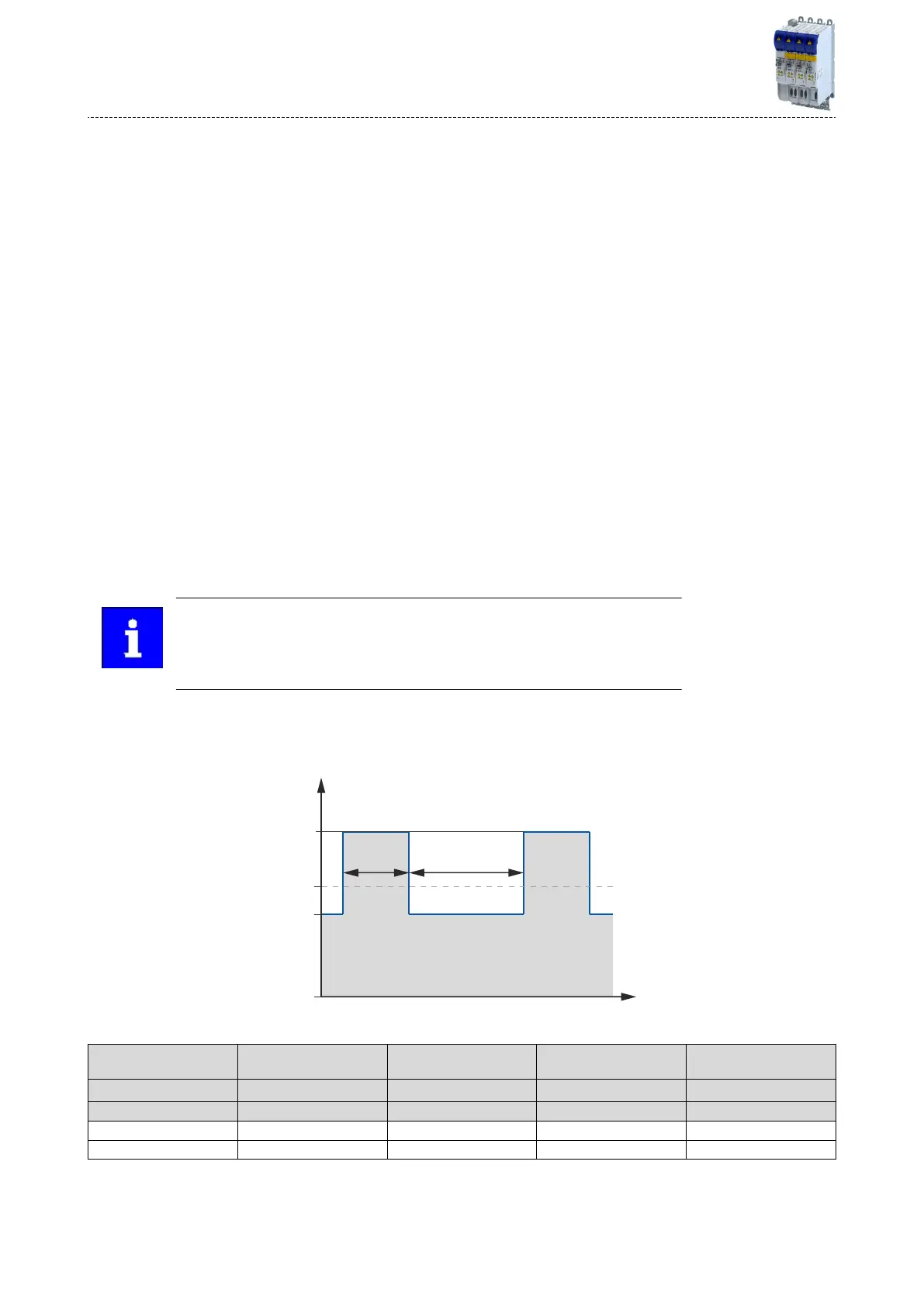
The graphics shows a cycle. The basic c
ondions given in the table (graphics eld highlighted
in grey) have to be complied with in order that the inverter will not be overloaded. Both cycles
can be combined with each other.
Overcurrent cycle Max. output current Overload me
Max. output current during
the r
ecovery me
Recovery me
A T
1
B T
2
s % s % s
Overcurrent cycle 15 s 200 3 75 12
Overcurrent cycle 180 s 150 60 75 120
Informaon on pr
oject planning
Project planning process
Overcurrent operaon
32
 Loading...


