Braking oper
aon
If more regenerave power is generated in an inverter in the DC system than can be stored in
the DC bus of the inverter, this excess energy is used by the other inverters in the DC-bus
connecon.
If there are operang states in which excess regenerave energy is generated for the enre
DC-bus connecon, an addional brake resistor must be used at the supplier. This avoids the
disconnecon of the DC-bus connecon due to too high DC-bus voltage. The excess energy is
converted into heat in the brake resistor.
NOTICE
Overheang of the br
ake resistor due to overload
Possible consequences: Destrucon of the brake resistor or the supplier.
▶
If you use non-intrinsically safe brake resistors: If the thermal contact responds, the voltage
supply to the supplier must be disconnected (e.g. switch o the control of the mains
contactor).
▶
Use intrinsically safe brake resistors.
Precondions f
or trouble-free braking operaon
•
Check whe
ther sucient braking power is available from the brake chopper in the supplier
for the maximum regenerave power occurring in all operang states.
•
When designing for connuous braking power in the DC bus, the liming monitors must be
included:
•
Monitoring the brake chopper
•
Monitoring the brake resistor
•
Increasing the braking power:
•
You can use several suppliers with brake chopper and brake resistor in parallel.
•
One supplier must be dened as "master", all other suppliers as "slave".
•
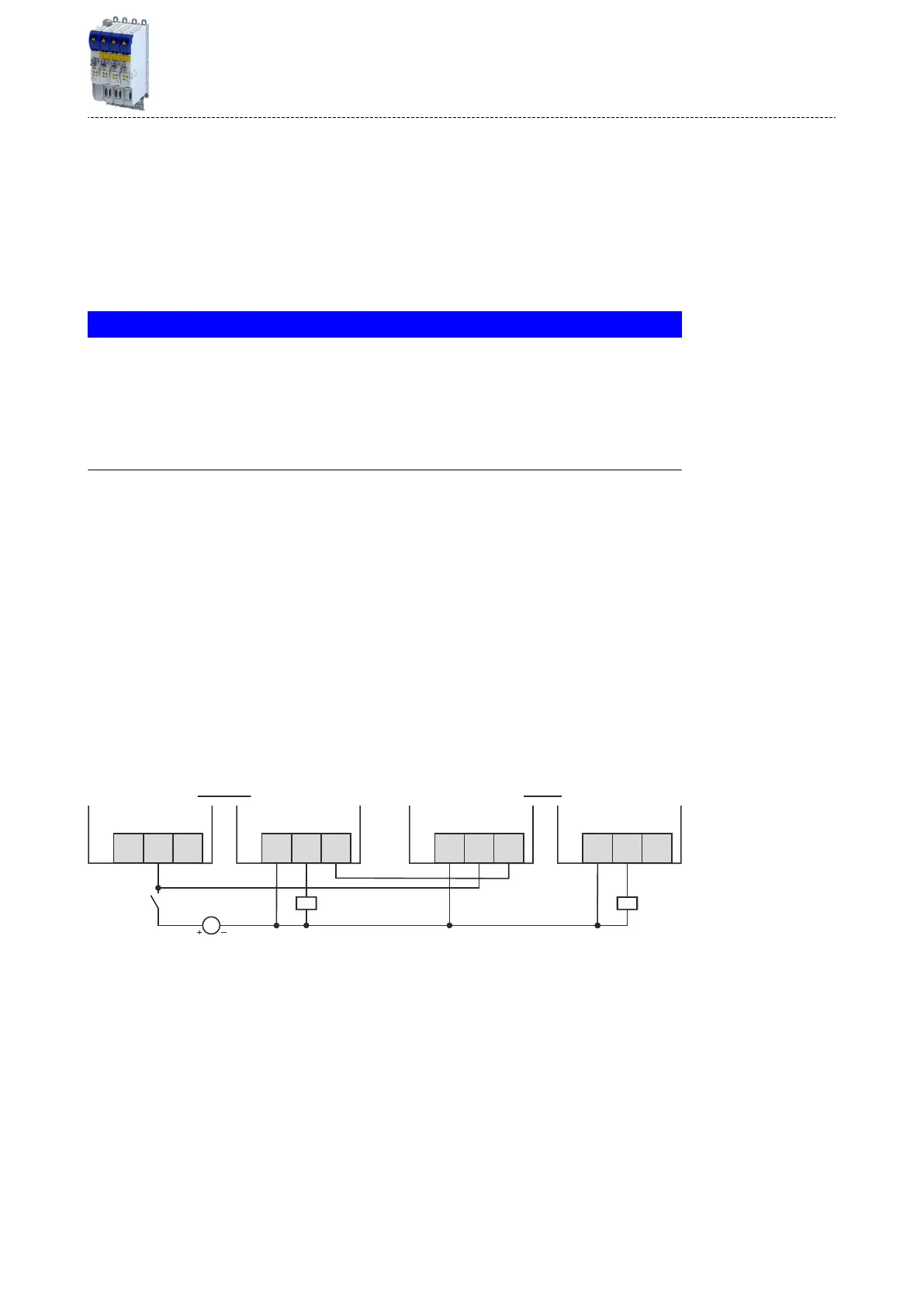
Adjust the wiring of the control terminals to ensure simultaneous switching of all brake
choppers on request of the master:
Connect the digital input DI3 of each slave to GND potenal.
Connect the digital output DO1 of the master with DI1 of the slaves.
X20.2 X20.2
DO1DO2GD
X20.1
DI1DI2
DI3
Master
Slave
|
DC 24 V
(.19.2...+28.8V)
DI1DI2
DI3
DO1DO2GD
X20.1
Fig. 5: Master-slave wiring of the brake chopper with suppliers connected in parallel
Informaon on pr
oject planning
DC-bus connecon
Braking operaon
39

 Loading...


