Manitowoc Published 03-29-17, Control # 064-23 3-53
14000 OPERATOR MANUAL OPERATING CONTROLS AND PROCEDURES
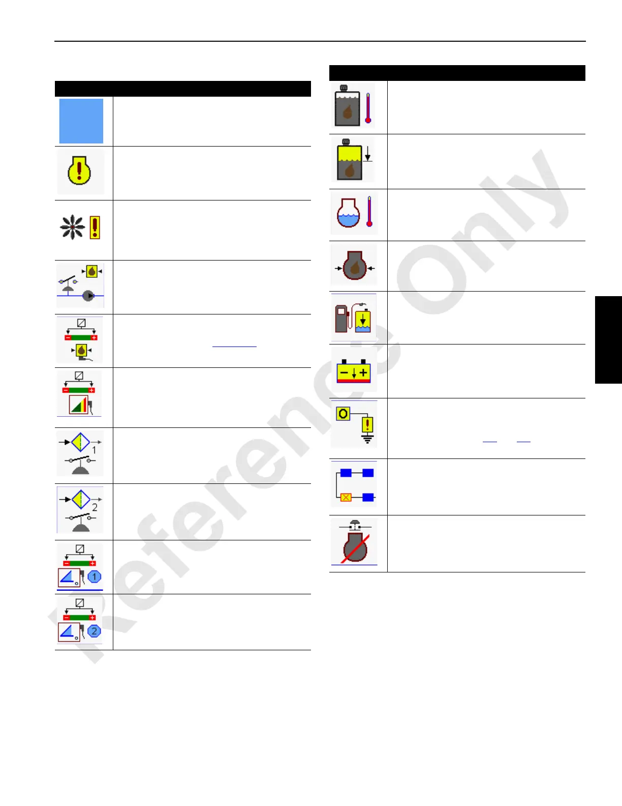
Table 3-5 System Faults
Item Description
0-No Fault.
10-Engine Alert Prompt — service Tier 3 engine
immediately.
See Engine Information Screen
in this section to determine fault.
30-Hydraulic Fan — Indicates a short in the fan
pump wiring or the fan pressure sender is out of
range. Fault 84 (Digital Output Disable) or Fault
41 (Transducer Voltage) will turn on at the same
time.
40-Hydraulic Vacuum Switch — Suction vacuum
has increased above 5 inches Hg.
41-Transducer Voltage — One or more hydraulic
pressure sensors are out of range. Perform
pressure sender test on
Page 3-68.
42-Rated Capacity Indicator/Limiter Sensor
Voltage— If a load sensing pin or load sensing
sheave are not within allowable range — high or
low, programmable controller will prevent crane
operation.
61-Filter 1 — Return Filter
— Filter is dirty or plugged.
Replace element or clean filter.
62-Filter 2 — Suction Filter
— Filter is dirty or plugged.
Replace element or clean filter.
63-Boom Angle Sensor — Boom angle sensor is
out of normal range (0.15 to 4.85 Volts).
64-Jib Angle Sensor — Luffing jib angle sensor
is out of normal range (0.15 to 4.85 Volts).
65-Hydraulic Fluid Temperature — Fluid
temperature in hydraulic tank is below 70°F
(21°C) or above 180°F (82°C).
69-Hydraulic Fluid Level Low — Hydraulic oil at
60% full hot or cold. Fill tank.
70-Engine Coolant Temperature — Engine coolant
temperature above 225°F (107°C). Engine will
automatically de-rates itself if this temperature is
reached.
71-Engine Oil Pressure Low — Oil pressure
below 7.25 psi (0,5 bar).
75-Fuel Level Low — Five percent fuel
remaining in tank. Fill tank as soon as possible
to prevent engine stoppage.
78-Battery Voltage Low — Battery voltage below
18 volts. Determine cause of fault and correct.
84-Digital Output Disable Fault — Digital output
signal has a short circuit between computer
node and output device. See CAN Bus screen
information and Tables
3-6 and 3-9 to identify
problem component.
85-CAN bus Communication Error — One or
more computer nodes are not communicating
correctly. See CAN Bus screen to identify
node(s).
88-Remote Emergency Shutdown — Remote
emergency stop shut down switch is pushed.
Pull switch up to reset and allow engine to start.
Item Description

 Loading...


