Manitowoc Published 03-29-17, Control # 064-23 v2 4-59
14000 OPERATOR MANUAL SETUP AND INSTALLATION
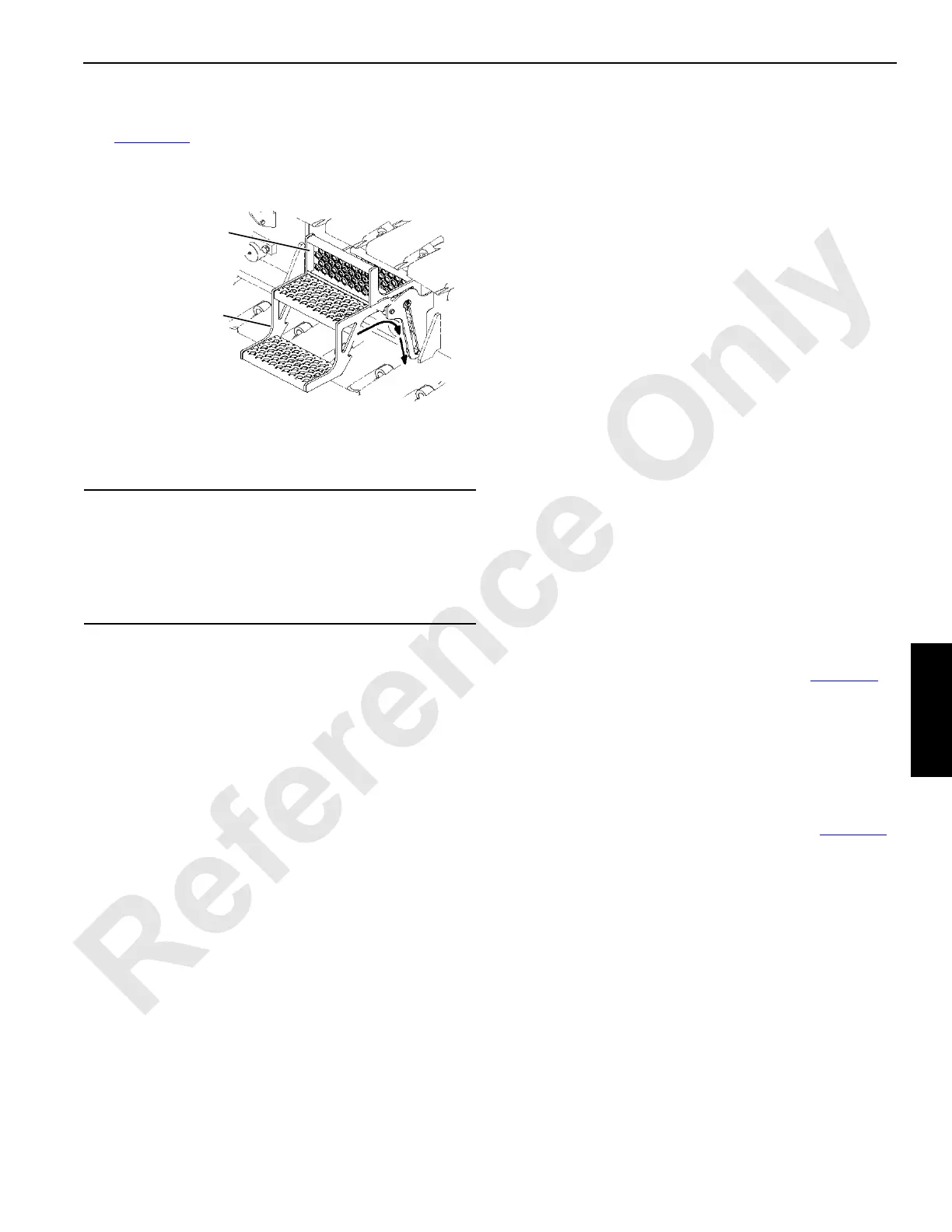
Remove Crawlers
See Figure 4-26 for the following procedure.
1. Rotate each crawler step in and down from working
position to stored position.
2. If equipped with automatic crawler lube system,
disconnect each grease line (1a, View A) from (1b) at
bracket (2) on carbody.
3. For S/N 14001001, 14001002, and 14001004 through
14001010, disconnect and store travel brake hydraulic
hoses in following order at both crawlers:
a. Disconnect hydraulic hose (3, View F) from coupler
(7) on carbody.
b. Connect hydraulic hose (3, View G) to coupler (6)
on crawler.
c. Disconnect hydraulic hoses (4 and 5, View F) from
couplers (7) on carbody.
d. Connect hydraulic hoses (4 and 5, View G) to each
other and lay in slot in bracket (8).
4. For S/N 14001001, 14001002, and 14001004 through
14001010, perform following steps at both crawlers:
a. Remove pin (9, View E) and slide guard (10) away
from carbody to expose drive shaft (11, View D1).
b. Remove screws (12, View D1).
c. Lift drive shaft (11, View C) onto bracket (13).
d. Apply a coat of light oil or rust inhibitor to mating
surfaces of drive shaft flanges.
e. Install screws (12, View D1) in motor flange (14b)
holes.
f. Install pin (9, View C) in guard (10) holes.
5. For S/N 14001003, 14001011 and newer, perform
following steps at both crawlers:
a. Remove pin (9, View E) and slide guard (10) away
from carbody to expose retainer (15, View D2).
a. Remove screws (16, View D2).
b. Slide retainer (15, View D2) onto drive shaft (11).
c. Lift drive shaft (11, View C) onto bracket (13).
d. Apply a coat of light oil or rust inhibitor to mating
surfaces of retainer (15), spacer (18), and motor
flange (17).
e. Install screws (16, View D2) in motor flange (17)
holes.
f. Install pin (9, View C) in guard (10) holes.
6. Position each carbody jack as follows (see Figure 4-8
):
a. Remove hitch pin (7, View E).
b. Swing jack out (View F).
c. Install hitch pin (7).
d. Remove jack pads (8, View D) and attach to jacks
(8, View F).
7. Using controls on front of carbody (View A, Figure 4-8
),
extend all four jacks until crawler treads are just clear of
ground. Keep crane level while jacking.
CAUTION
Parts Damage
To avoid damage to travel brakes on S/N 14001001,
14001002, and 14001004 through 14001010, hydraulic
hoses must be connected in stored position (View G)
when shipping crawlers.
FIGURE 4-26 continued
Crawler Step
(Working Position)
Crawler Step
(Stored Position)
14COM4121

 Loading...


