Manitowoc Published 03-29-17, Control # 064-23 3-27
14000 OPERATOR MANUAL OPERATING CONTROLS AND PROCEDURES
F – Load Drum Controls
See Figure 3-13 for the drum and handle identification.
Each load drum has a spring-applied, hydraulically-released
disc brake on motor at one end of drum.
Additionally, if the front or rear drum has free fall, a spring-
applied, hydraulically-released disc-type clutch/brake is
provided on the right end of drum.
For normal operation (free fall off):
• Corresponding drum brake is released automatically
when drum handle is moved in either direction from off
• Corresponding drum brake is applied automatically
when drum handle is moved to off
For FREE-FALL operation:
• The disc brake (on left end of drum) is applied at all
times
• The corresponding clutch/brake (on right end of drum) is
spring applied when the drum handle is moved from off
to hoist or lower the load with full power
• The corresponding clutch/brake is released when drum
handle is moved to off. Use drum working brake to
control lowering speed and to stop and hold load in
position
NOTE: Drum brakes are applied automatically when
engine is stopped (or power is lost for any reason),
applicable operating limits are reached, applicable
system faults occur, or drum park switch is on.
F1. Drum 1 (Front Drum) Park Switch
F2. Drum 2 (Rear Drum) Park Switch
F3. Drum 3 (Auxiliary/Luffing Jib) Park Switch
Press TOP of rocker to TURN ON corresponding drum park
switch. With drum park switch on, drum handle is inoperable,
drum brake is applied, and (if equipped) drum pawl is
engaged.
Press BOTTOM of rocker to TURN OFF drum park switch.
With drum park off, drum handle is operable, drum brake is
applied and released in conjunction with handle movement,
and (if equipped) drum pawl is disengaged.
F4. Drum 1 (Front Drum) Handle
F5. Drum 2 (Rear Drum) Handle
F6. Drum 3/4 (Auxiliary/Luffing Jib) Handle
See Figure 3-12 for the drum and handle identification.
The following description is for standard operation (free fall
off) If free fall is on, corresponding drum working brake
must be applied to stop load when drum handle is
released to off.
Pull handle BACK to HOIST load. Drum brake releases and
speed increases in relation to handle movement.
Release handle to CENTER to STOP load. Drum brake
spring applies.
Push handle FORWARD to LOWER load. Drum brake
releases and speed increases in relation to handle
movement.
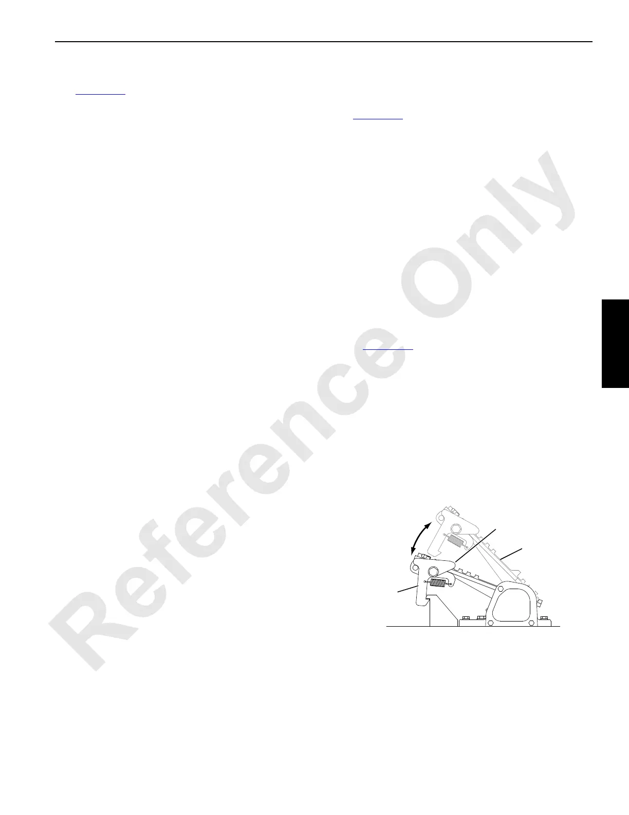
F7. Drum 1 (Front Drum) Working Brake Pedal
F8. Drum 2 (Rear Drum) Working Brake Pedal
Each free fall equipped drum has a spring-applied,
hydraulically-released working brake controlled by a brake
pedal (Figure 3-14
). When free falling a load, working brake
must be used to slow down and stop the load.
The brake pedals have no function and are inoperable when
operating in full power.
DEPRESS pedal to APPLY working brake in relation to pedal
movement. Fully depress and latch pedal to fully apply
brake.
DEPRESS heel of latch to unlatch pedal and then RELEASE
pedal (ease up) to RELEASE the working brake gradually as
pedal rises.
FIGURE 3-14
Pedal
Brake
Applied
Brake
Released
A1182
Latch
Press Here
to Unlatch

 Loading...


