OPERATING CONTROLS AND PROCEDURES 14000 OPERATOR MANUAL
3-36
Published 03-29-17, Control # 064-23
Boom Hoist Operation
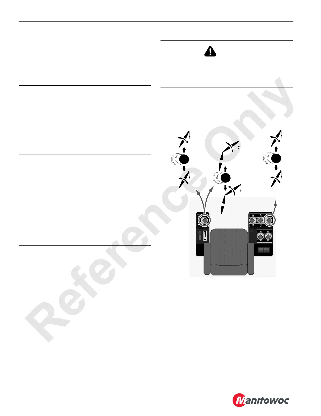
See Figure 3-21 for the boom hoist operation.
In standard configuration boom hoist handle is on the left
console. When crane is configured with a luffing jib, boom
hoist handle is the last load drum handle 3/4 on right
console.
1. Select crane configuration and capacity charts on Rated
Capacity Indicator/Limiter display, Configuration screen.
2. Turn off Drum 4 park switch. Drum 4 pawl disengages
from drum when park switch is moved to off.
3. Increase engine speed to desired rpm with hand throttle.
Depress foot throttle to momentarily increase engine
speed when more power is required.
4. See Figure 3-21
. Push boom hoist handle FORWARD
from off to LOWER boom or pull handle BACK from off to
RAISE boom.
5. As boom nears desired angle, slowly move handle
toward off to decrease speed. Then move handle to off
to stop boom and hold it in position and brake will apply.
NOTE: Besides a boom up limit, a physical boom stop
cushions boom raising between approximately
77.6° and maximum angle. Boom stop also
provides a physical stop at 89.5°.
6. Turn on park switch if boom angle will not be changed.
Drum 4 pawl engages into drum when park switch is
moved to on.
CAUTION
Avoid Rigging Damage!
Check that boom hoist wire rope is reeved through all
sheaves and spooled properly onto drum before raising
boom from ground.
• See Boom Rigging Drawing in Section 4 for wire rope
and reeving specifications
• See Wire Rope Installation in Section 4 for
instructions on attaching wire rope to boom
CAUTION
Avoid Boom or Jib Damage!
Do not turn on drum park switch while raising or lowering
boom; brake will bring boom to an abrupt stop. This action
could cause shock load damage to boom and jib. Bring
boom to a smooth stop with handle and then turn on drum
park switch.
WARNING
Avoid Two-Blocking Hazard!
Pay out load lines while lowering boom. Load may contact
boom point or jib point sheaves if this step is not taken.
Wire rope or other parts could break allowing load to fall.
FIGURE 3-21
Drum 3
Luffing Jib
C
onfiguration
OFF
Raise
Boom
Lower
Boom
Drum 4
Standard
Configuration
Raise
Jib
Lower
Jib
Drum 4
Luffing Jib
Configuration
OFF
Lower
Boom
Raise
Boom
OFF
14COM3-10

 Loading...


