SETUP AND INSTALLATION 14000 OPERATOR MANUAL
4-6
Published 03-29-17, Control # 064-23 v2
OPERATING CONTROLS
To assemble and disassemble the 14000 with the self-
erecting system, the engine must be running and
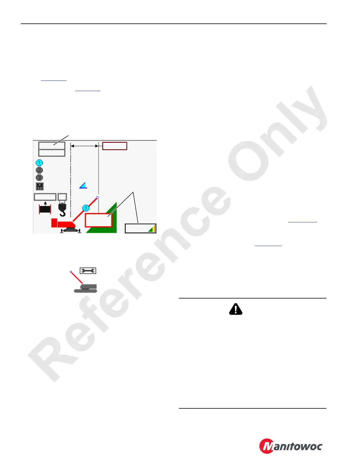
LIFTCRANE MAST CAPACITIES CHART must be selected
in the configuration screen of the Rated Capacity Indicator/
Limiter (Figure 4-4
).
The setup mode icon (Figure 4-5
) will appear in the fault area
of the information screen and the fault alarm will beep on and
off (beep–beep–beep...).
See Section 3 for remote control operating instructions.
The crane’s programmable controller automatically
increases engine speed to approximately 1,300 rpm (if
engine is running slower) when any accessory function is
operated. If engine speed is set higher than 1,300, the
existing speed is maintained. The accessory functions are:
• Carbody Jacks
• Crawler Pins
• Gantry Cylinders
• Mast Arm Cylinders
• Boom Hinge Pins
• Cab Tilt Cylinder
PRE-START CHECKS
Make the following checks before starting the engine upon
arrival at the assembly site. See Section 3 for starting
instructions.
Engine
1. Check for leaks.
2. Check fuel, oil, and coolant levels.
3. Repair or refill as required.
Gear Boxes
1. Check for leaks.
2. Check levels.
3. Repair or refill as required.
Hydraulic System
1. Check for leaks.
2. Check level.
3. Repair or refill as required.
4. Make sure hydraulic shut-off valve is open.
Electric System
Check that electric cable (2a, View B, Figure 4-8) is
connected terminating plug (1).
If equipped with a boom butt drum with bail limit, make sure
terminating plug (1, View C, Figure 4-8
) is connected to
electric cable (2b).
The crane’s controls may not operate properly and faulty
readings may appear on the main display if this step is not
performed.
If the engine will not start, make sure the setup remote
control stop switch is not depressed.
-0.0T
00.0 T
2
+60.0°
8.3 M
0000 AM
00.0 T
142.9 T
4.6 M
FIGURE 4-4
Liftcrane Mast Capacity Chart Number
(see End of This Section)
Operator Beware:
Load being lifted is not
indicated when using mast
as a boom. These boxes
will always read 0.
14COM4102
FIGURE 4-5
Setup Mode
Icon
14COM4102a
WARNING
Burn and Inhalation Hazards!
Temperature of exhaust and exhaust components for
Tier 4 engines can be higher than other engines.
To prevent death or serious injury:
• Avoid physical contact with exhaust gases and
exhaust system components
• Keep all flammable materials away from the exhaust
system to prevent fire
• If necessary to service crane while engine is running,
inhibit (turn off) DPF regeneration using switch in cab
to prevent higher exhaust temperatures

 Loading...


