Manitowoc Published 03-29-17, Control # 064-23 v2 4-25
14000 OPERATOR MANUAL SETUP AND INSTALLATION
Install Crawlers
See Figure 4-12 for the following procedure.
NOTE: Each time the crawlers are assembled to the
carbody, thoroughly clean and apply Never-Seez
®
or equivalent anti-seizing compound to all
machined surfaces on the carbody and the
crawlers — surfaces marked Q in Views G and H.
If this step is not performed, excessive friction will
occur in the closely machined mating surfaces
between the crawlers and the carbody. The result
will be loud noises coming from the lowerworks
when turning (cutting) the crawlers or swinging the
upperworks over the corner of the crawlers.
1. Position trailer with crawler (1) along desired side of
crane (View A).
NOTE: The crawlers are interchangeable from one side to
the other.
Position the crawler drive shafts at the proper ends
of the carbody — left side to rear; right side to front.
Carbody remote controls (View B) are at front of
carbody.
2. Remove hitch pins (6, View E) and collars (7) from
crawler connecting pins (8).
3. Use center handles on carbody remote control (5a and
5b, View B) to retract crawler connecting pins (8, View
E).
4. Attach three hooks from chain sling (2, View C) to lifting
links (3) on outboard side of crawler and to lifting lug (4)
on inboard side of crawler.
5. Slowly hoist crawler clear of trailer and remove trailer.
6. Slowly lower crawler, boom up, and swing to engage
hooks (9, View F) on crawler with fixed pins (10) in
carbody.
7. STOP lowering and booming when crawler hooks are
engaged with fixed pins and connecting holes (12 and
13, View F) are aligned.
8. Engage crawler connecting pins (8, View E) and install
collars (7) and hitch pins (6).
DANGER
Falling Load Hazard!
Prevent structural failure of components while handling
either crawler with mast:
• Make sure crane is level. Check level on front of
carbody. Adjust jacks as required
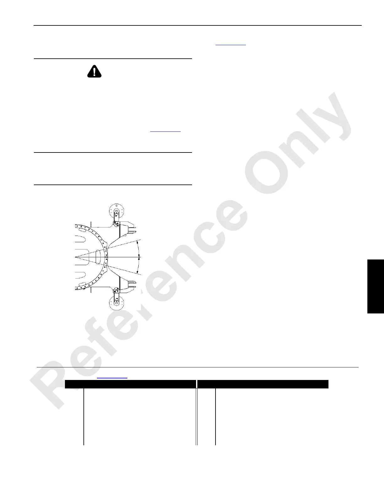
• Do not swing 15° either side of center (Figure 4-13
)
• Do not exceed lifting capacities given in Liftcrane
Mast Capacities Chart
CAUTION
Parts Damage!
Avoid hitting carbody jacks with crawlers.
Swing Diagram
FIGURE 4-13
15°
15°
Centerline
14COM4119
Legend for Figure 4-12
Item Description Item Description
1 Crawler 7 Collar
2 Chain Sling (4 Leg) 8 Crawler Connecting Pin
3 Lifting Link 9 Hook
4 Lifting Lug 10 Fixed Pin
5a Left Crawler Pins Control 11 Carbody
5a Right Crawler Pins Control 12 Crawler Connecting Hole
6 Hitch Pin with Hair Pin Cotter 13 Carbody Connecting Holes

 Loading...


