OPERATING CONTROLS AND PROCEDURES 777 OPERATOR’S MANUAL
3-44 Published 10-01-12, Control # 044-05 v2
PROGRAMMABLE CONTROLLER
CALIBRATION PROCEDURES
General
To ensure proper operation of the crane functions, the
controls and pressure senders must be properly calibrated
as described below.
Controls Calibration
The controls must be calibrated at the following intervals:
• When a pump is replaced.
• When a pump control (EDC or PCP) is replaced.
• When a boom hoist cylinder is replaced.
• When a new programmable controller is installed.
• When a new CPU board is installed.
• When a new controller chip is installed.
• When there is a noticeable increase in the time it takes a
crane function to engage when the handle is pulled back
from off.
• Every 6 months.
To calibrate the controls, proceed as follows:
To calibrate the controls, proceed as follows:
1. Engage swing lock.
2. Calibrate pressure senders.
3. Start and run engine at:
• 1,900 rpm or higher for past production units (Tier 1
engine).
• 1,600 rpm or higher for current production units (Tier
2 and 3 engine).
4. Depress and hold swing holding brake switch (on swing
handle) for ONE MINUTE.
5. Repeat steps 3 and 4 a second time.
Pressure Sender Calibration
The pressure senders must be calibrated (zeroed) at the
following intervals:
• When a new programmable controller is installed.
• When a new CPU board is installed.
• When a new controller chip is installed.
• When a pressure sender is replaced (see Pressure
Sender Replacement in Section 2 of Service Manual).
• When displayed pressure is wrong.
• Every 6 months.
To calibrate the pressure senders, proceed as follows:
1. Stop engine.
2. Turn ON cab power switch.
3. Turn crane mode selector key counterclockwise to
CONFIRM position and hold.
4. Press engine run/stop switch to RUN position.
5. Continue to hold crane mode selector key in CONFIRM
position for ONE MINUTE after performing step 4.
6. Confirm that pressure senders are properly calibrated by
checking charge pressure on diagnostic screens of
digital display (refer to Diagnostic Display publication in
Operator’s Manual):
a. With engine off (key in RUN), charge pressure for
each crane function should be 50 psi (3.4 bar) or
less.
b. With engine running, charge pressure for each
crane function should be within normal operating
range – approximately 275 (19.0 bar) at low idle to
400 psi (27.6 bar) at high idle.
DIGITAL DISPLAY READINGS
The digital display and selector (see Operating Controls in
this section) allow operator to monitor three groups of crane
information: operating conditions, operating limits, and
system faults.
Depress top or bottom of selector to scroll up and down
through the display readings. Release selector when desired
information is displayed.
To display diagnostic operating conditions listed in Table 3-3,
depress limit bypass switch while scrolling up with selector.
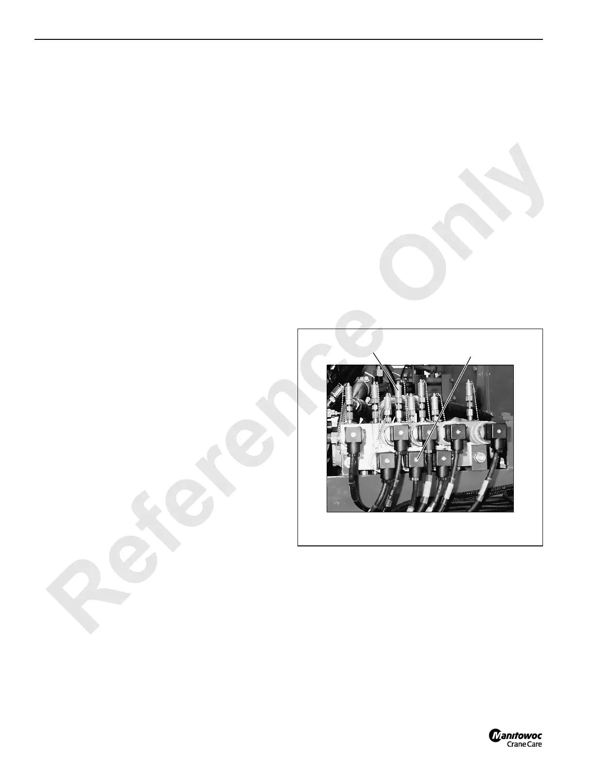
FIGURE 3-26
Boom Hoist Cylinder
Pressure Sender
Left Side of Pumps
Gauge
Coupler
P697

 Loading...


