SET-UP AND INSTALLATION 777 OPERATOR’S MANUAL
4-12 Published 10-01-12, Control # 044-05
Install Counterweights
The crane rotating bed must be in-line with carriage while
installing upper counterweight (360° swing is permitted while
assembling counterweights and installing carbody
counterweights).
1. Check that both counterweight limit switches are
properly installed at rear of crane and operational. Test
both limit switches as instructed in Counterweight Limit
Switch Adjustment in Crane Service Manual.
2. Assemble upper counterweights as shown in Figure 4-8,
Views A and B:
a. Lift lower tray onto ground and level it with blocking.
Lift at four lifting lugs on lower tray (Figure 4-8, View
A or B).
NOTE: Rollers on lower tray must face crane.
b. Lift side boxes into position and pin to lower tray
(Figure 4-8, View A-A) — lift at connecting pins
c. Lift remaining side boxes into position and pin to
each other (Figure 4-8, View A-A).
d. On current production cranes using Model 888 or
999 side boxes, be sure to pin steel plates to both
top side boxes (Figure Figure 4-8, View B).
WARNING
Tipping Crane Hazard!
Prevent crane from tipping while assembling
counterweights:
• Do not exceed 26 ft (7.9 m) radius.
• Do not lift more than 40,000 lb (18 144 kg). Tipping or
structural damage may occur.
• Install Series-2 counterweight in exact sequence
given in this procedure and shown in Figure 4-9,
View A.
Avoid dropping counterweights during assembly:
• Do not lift lower tray and side boxes as a unit. Lifting
lugs may break.
• Do not lift more than two side boxes at a time. Lifting
lugs may break.
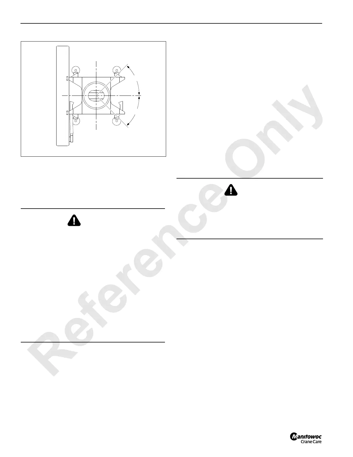
da0102.ai
45°
45°
FIGURE 4-7
WARNING
Tipping Crane Hazard!
Prevent crane from tipping on current production cranes
using Model 888 or 999 side boxes:
• Pin steel plates to both top side boxes as shown in
Figure Figure 4-8, View B.

 Loading...


