Manitowoc Published 10-01-12, Control # 044-05 4-25
777 OPERATOR’S MANUAL SET-UP AND INSTALLATION
4
16. Lower butt onto blocking approximately 15 in. (381 mm)
high (Figure 4-14).
17. Unpin upper wire rope guide from lower wire rope guide
(Figure 4-14, View B). Use same pins in step 19.
18. Lower mast (boom down) until upper wire rope guide is
fully lowered.
19. Pin upper wire rope guide to boom butt (Figure 4-14,
View C).
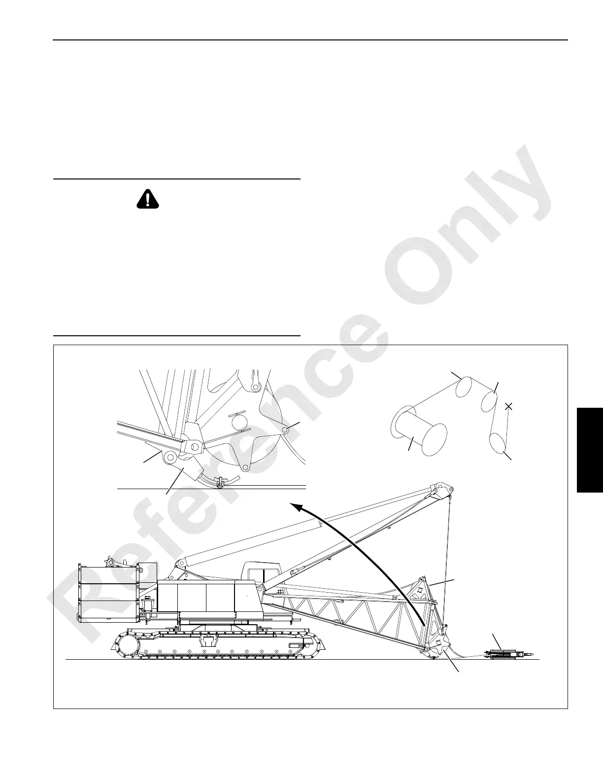
Install Assembly Block
1. Boom down until upper wire rope guide sheave is 2 – 3 ft
(0.6 – 0.9 m) off ground as shown in Figure 4-15,
View A.
2. Place assembly block on ground in front of boom butt
(Figure 4-15, View A).
3. Reeve wire rope from rear drum over both guide
sheaves in boom butt and sheave in assembly block
(Figure 4-15, View B).
NOTE: Install rope guide bar in proper holes as shown in
Figure 4-14, View C.
4. Anchor wire rope to socket and wedge and connect to
lug on boom butt (Figure 4-15, View C) (see Wire Rope
Installation and Maintenance in Section 5 in this
manual).
5. Boom up to raise boom butt to desired angle.
6. Connect 4-leg chain sling to assembly block.
DANGER
Falling Load Hazard!
Do not remove upper wire rope guide connecting pins
until following steps are performed:
• Rigging pendants are securely attached between
mast and upper wire rope guide.
• Rigging pendants are tensioned enough to support
weight of upper wire rope guide.
Upper wire rope guide will fall violently if these steps are
not performed before pins are removed.
FIGURE 4-15
View B
View C
View A
Lug
Socket
and Wedge
A985a
Lower
Wire Rope
Guide
Rear
Drum
Assembly
Block
Upper
Wire Rope
Guide
Lower
Wire Rope
Guide
Upper
Wire Rope
Guide
Assembly
Block
Wire Rope
Guide Bar

 Loading...


