SET-UP AND INSTALLATION 777 OPERATOR’S MANUAL
4-48 Published 10-01-12, Control # 044-05
Install Jib
See Jib Rigging Guide in this section for jib installation
instructions. Upper boom point must be removed prior to jib
installation.
Connect Boom Butt to Boom
See procedure earlier in this section.
Install Load Line
See Load Line Reeving in this section for proper routing and
reeving of load lines.
Manitowoc recommends installation of the cage-type rope
guard (Figure 4-28, View C-C) for all duty-cycle operations
(clam, drag, pile driving). The rope guard will protect the
sheaves from side-load damage.
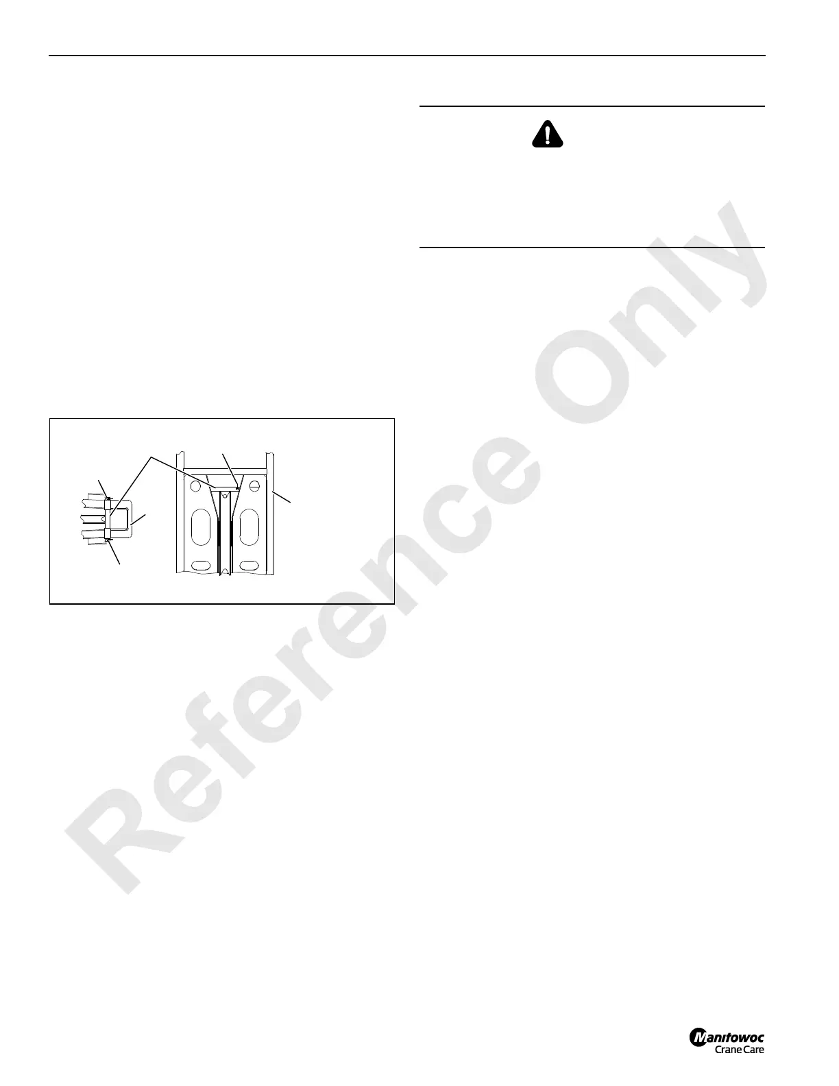
On current production jibs, remove the rope guards
(Figure 4-30) to pull the load line through the jib point and
strut without removing the socket and wedge.
Install Block-Up Limit Control
Install block-up limit components and connect electrical
cords as shown in Block-Up Limit Control Assembly Drawing
at the end of this section.
See Section 5 of the Crane Service Manual for adjustment of
the limit switches.
Install Rated Capacity Indicator/Limiter Components
Install rated capacity indicator/limiter components and
connect electrical cords as shown in Rated Capacity
Indicator/Limiter Assembly Drawing at the end of this section
for installation.
Install Wind Speed Indicators
Install wind speed indicator components and connect
electrical cords as shown in Wind Speed Assembly Drawing
at the end of this section.
Perform Pre-raising Checks
Perform the pre-raising checks given earlier in this section.
Boom Removal
Store Load LInes
Disconnect load lines from load block and from hook-and-
weight balls.
Spool load lines onto load drums for storage.
Remove Electrical Components from Boom and Jib
Disconnect applicable electrical cables and remove
electrical components from boom and jib:
• Block-up limit components (see Block-Up Limit Control
Assembly Drawing at end of this section).
• Rated capacity indicator/limiter components (see Rated
Capacity Indicator/Limiter Assembly Drawing at end of
this section for installation).
• Wind speed indicator components (see Wind Speed
Assembly Drawing at end of this section).
Disconnect Boom Butt from Boom
See procedure earlier in this section.
Install Assembly Block
See procedure earlier in this section.
The 777 can be used to disassemble the boom and jib.
Remove Jib
See Jib Rigging Guide in this section for jib removal
instructions.
Remove Upper Boom Point
1. Remove upper connecting pins and snap pins at holes A
(Figure 4-28, View C).
2. Remove upper boom point from end of boom top.
Disconnect Pendants
Disconnect boom pendants from each other (Figure 4-28,
View B) and, if equipped, from intermediate suspension strut
(Figure 4-29, View D). Lay pendants on top of boom.
NOTE: When disassembling the boom, the pendants can
be left on top of the inserts for shipping. This
FIGURE 4-30
Jib
Strut
A00953
Jib
Top
Wire Rope
Guard
Snap Pin
Snap Pin
Snap Pin
WARNING
Falling Jib Hazard!
Visually observe that jib stop pins fully engage holes in jib
stop frame as boom and jib are raised from ground.
Jib can be pulled over backwards if jib stop pins do not
engage.

 Loading...


