Manitowoc Published 10-01-12, Control # 044-05 4-41
777 OPERATOR’S MANUAL SET-UP AND INSTALLATION
4
Blocked Crawlers
To prevent the crane from tipping, some boom and jib
lengths must be raised and lowered over blocked crawlers.
See capacity charts for blocked crawler requirements and to
Crawler Blocking Diagram in Capacity Chart Manual for
instructions.
Handling Components
Handle boom sections with care. Four lifting lugs are
provided on each section for handling with hooks, chain
sling, or slings (Figure 4-24).
If lugs are not used, nylon slings should be used to handle
boom sections. If wire rope or chain slings are used,
protective covering (such as sections of rubber tire) must be
used between the slings and the section. Lift against chords
only, never against lacings.
Boom handling for low clearance travel is limited. See the
chart in Figure 4-25.
Boom Rigging Assembly Drawing
Boom components (top, inserts, butt, pendants) must be
assembled in the proper sequence according to this topic
and the Boom Rigging Assembly drawing at the end of the
manual. See Figure 4-31 to determine the quantity and
length of inserts and pendants for various boom lengths.
When disassembling the boom, the pendants can be
disconnected and left on top of the inserts for shipping. This
arrangement allows the boom to be reassembled faster.
It is owner/user’s responsibility to securely attach
pendants to inserts so that pendants cannot fall off
inserts during shipment.
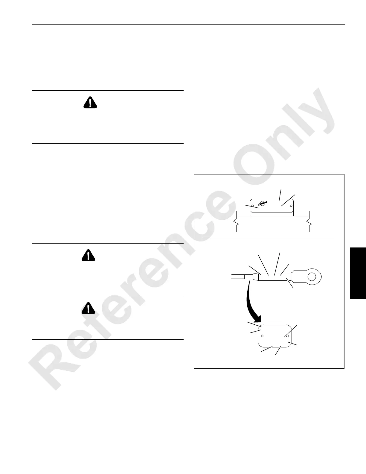
Identifying Boom Sections And Pendants
Boom sections are marked for proper identification as shown
in Figure 4-26, View A — Boom number, part number, and
manufacturing code are stamped into a plate mounted on all
four chords of each section.
Pendants are marked for proper identification as shown in
Figure 4-26, View B.
DANGER
Tipping Hazard!
Do not attempt to raise or lower boom and jib from or to
ground until crawlers are blocked, if required. Otherwise,
crane will tip.
WARNING
Falling Boom Hazard!
Do not attempt to handle more boom than shown in
Figure 4-25. Structural failure of wire rope guide could
result, possibly allowing boom to fall.
WARNING
Boom can only be picked up at butt. Structural failure of
wire rope guide could result if boom is picked anywhere
other than at butt.
FIGURE 4-26
PN-277360
PO-96858-90
SET-3
RL-6390B-01
1&1-4''X19.17'
6X25 EEIP RR IWRC
02518823 1 1/4 x 19 2 277360 968588-90
A524
Length
(feet and inches)
Diameter
(inches)
Manufacturer’s
Number
Manitowoc
Purchase Order
Number
Aluminum Tag
(if equipped)
Manitowoc
Part Number
Manitowoc
Part Number
Manitowoc
Purchase Order
Number
Length
(feet)
Diameter
(inches)
Rope Type
Manufacturer’s
Number
View A
View B
A524
#YY
Z-ZZ-ZZ
XXXXXX
Manufacturing
Code
Manitowoc
Part Number
Boom
Number
Chord

 Loading...


