OPERATING CONTROLS AND PROCEDURES 777 OPERATOR’S MANUAL
3-12 Published 10-01-12, Control # 044-05 v2
To set each thermostat, remove cover and turn knob
clockwise to 100°F (38°C).
Engine is equipped with a 1500 W block heater (120 V)
without a thermostat.
C12. Windshield Washer Switch
Depress and hold TOP end of rocker to SPRAY washing
solution onto upper front window.
RELEASE rocker to STOP spraying washing solution onto
upper front window.
NOTE: Washer tank is mounted in lower right corner of
operator's cab. Fill tank with a quality brand
washing solution that will not freeze during cold
weather.
D – Indicators
D1. Digital Display and Selector Switch
Allows operator to monitor three groups of crane information:
operating conditions, operating limits, and system faults. See
Digital Display Readings in this section for tables identifying
information which can be displayed.
Press top or bottom of selector to scroll up or down through
display readings. Release selector when desired information
is displayed.
D2. Operating Limit Alert
GLOWS YELLOW and a BUZZER comes ON to alert
operator that an operating limit has been reached (limit
automatically appears on digital display). See Digital Display
Readings for a list of operating limits, function responses,
and corrective actions.
D3. System Fault Alert
GLOWS RED and a BEEPER comes ON to alert operator
that a system fault exists (fault appears on digital display).
See Digital Display Readings for a list of system faults,
causes, function responses, and corrective actions.
D4. Rotation Indicators
Move UP and DOWN to signal the operator by feel, that
boom hoist, luffing hoist, or corresponding drum is turning.
NOTE: Rotation indicators are pin-type actuators located
under handle covers.
Indicator movement corresponds to hoist or drum speed
NOTE: Boom and load bounce while traveling or
performing other operations may cause boom hoist
rotation indicator to move up and down
occasionally, even if boom hoist is not being
operated.
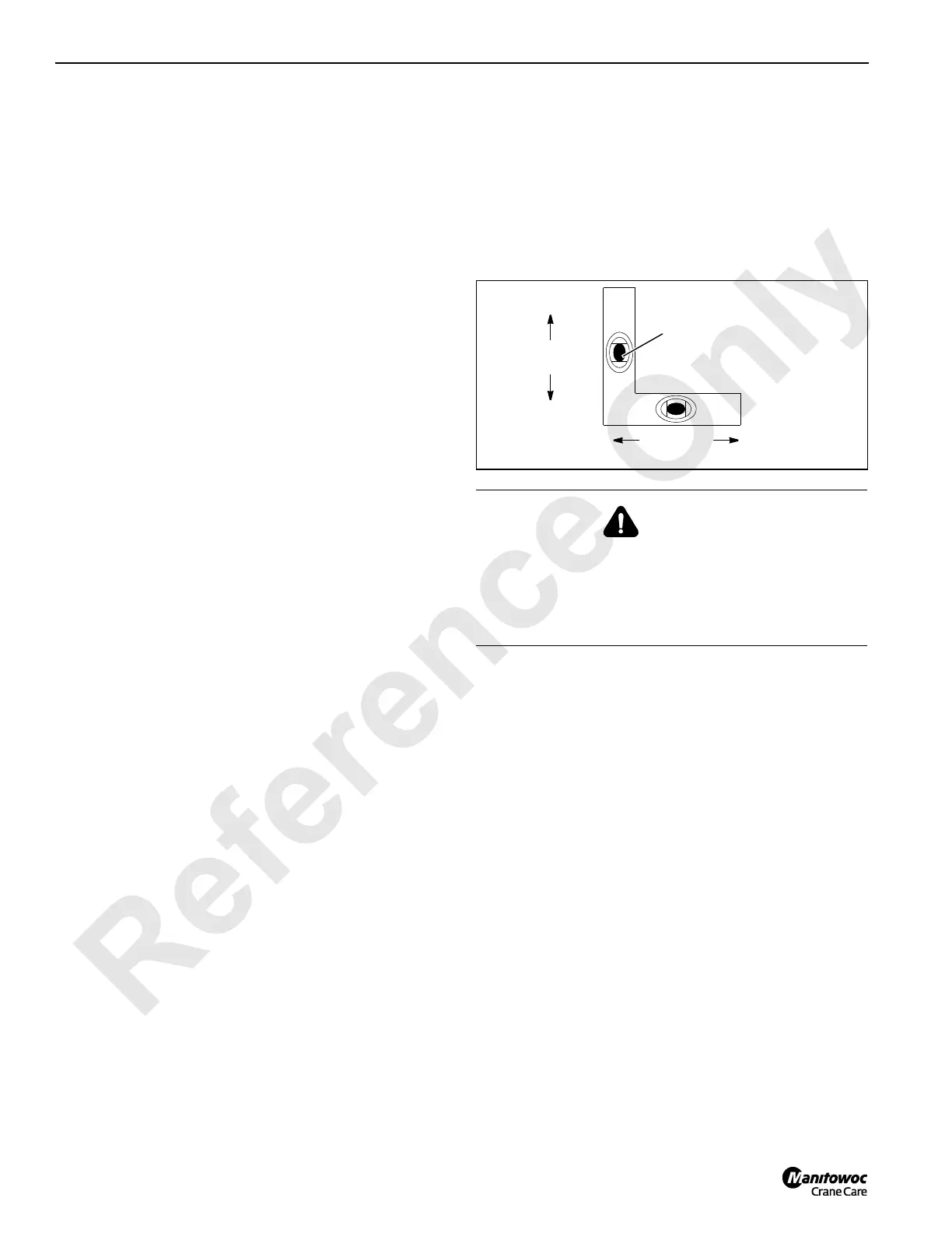
D5. Level
Indicates crane levelness from front to rear and from side to
side as shown in Figure 3-6. The level is mounted on front of
rotating bed and is visible through right side window in the
operator’s cab.
D6. Mirrors
One adjustable interior mirror lets operator view load drums.
Two adjustable exterior mirrors lets operator view to rear of
crane. Both mirrors can be rotated inward for shipping.
D7. Rated Capacity Indicator/Limiter Console
See separate Rated Capacity Indicator/Limiter Manual for
operation.
D8. Engine Hourmeter
Shows total number of hours engine has been run.
D9. Boom Angle Indicator
Shows angle of boom in degrees above horizontal. Boom
and luffing jib angles can also be viewed under OPERATING
CONDITIONS on digital display. See Figure 3-4 for
identification of various boom and luffing jib angles.
WARNING
Tipping Hazard!
Unless otherwise specified on capacity chart, all crane
operations must be performed with crane level to within
one percent of grade. Operating crane at a greater angle
could cause crane to tip.
FIGURE 3-6
Side-to-Side
A882
Levelness
Front-to-Rear
Levelness
Centered bubble
One half of bubble off center
indicates approximately one
percent of grade out of level
indicates level.

 Loading...


