Manitowoc Published 10-01-12, Control # 044-05 v2 3-9
777 OPERATOR’S MANUAL OPERATING CONTROLS AND PROCEDURES
3
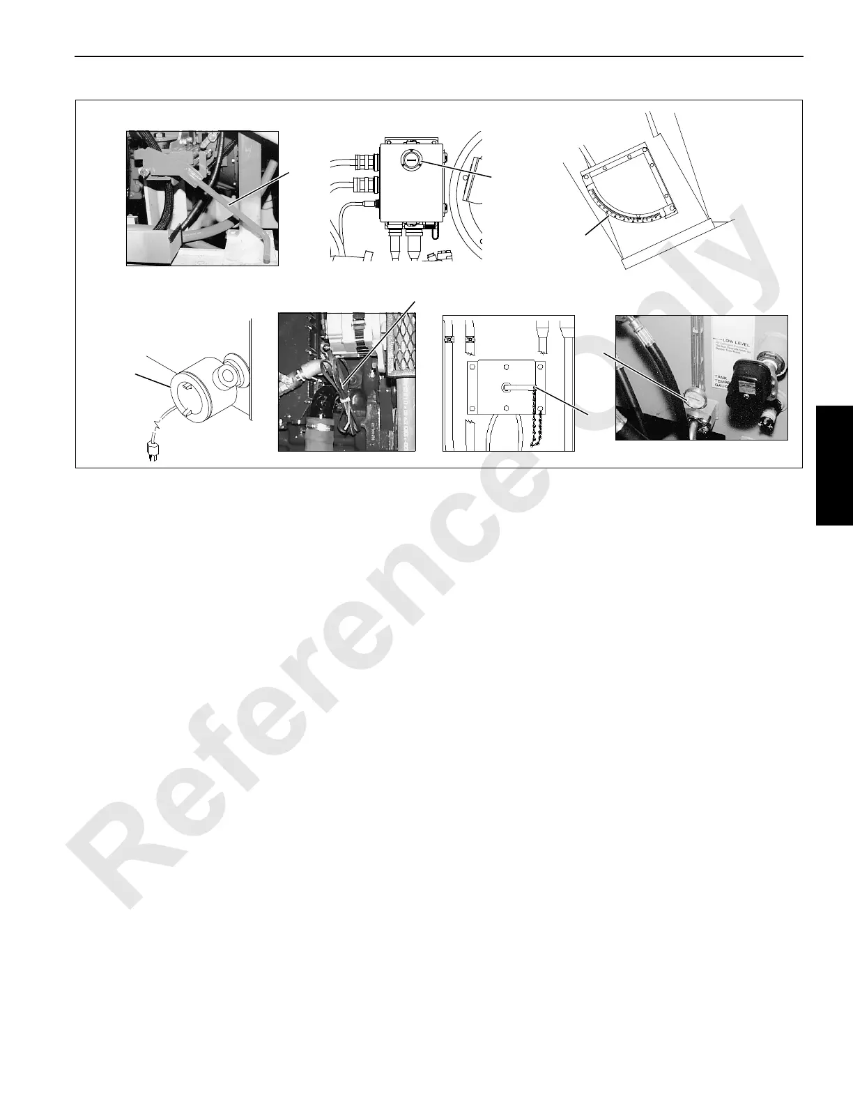
Legend for Figure 3-4
A976D9
P453a
A971
A1206
P450
C11
D8
B5
C11
E5
P454
Right Inboard
Leg of
Boom Butt
Front of
Hydraulic Tank
Left Side
of Engine
Left Side Compartment
Between Load Drums
Left Side
of Engine
Right Side and Rear
of Hydraulic Tank
Thermostat
Knob is Under
Cover
FIGURE 3-4 continued
A13892
Left Side of
Rotating Bed
B7
A — Power Controls D — Indicators H — Load Drum Controls
A1. Engine Ignition Switch D1. Digital Display and Selector Switch H1. Front Drum Handle
B — Engine Controls D2. Operating Limit Alert H2. Rear Drum or Luffing Jib Handle
B1. Engine Warning/Diagnostic Lights D3. System Fault Alert H3. Auxiliary Drum Handle
B2. Ether Starting Aid Switch (1) D4. Rotation Indicators H4. Front Drum Park Switch
B3. Engine Hand Throttle D5. Level H5. Rear Drum Park Switch
B4. Engine Foot Throttle D6. Mirrors (Interior and Exterior) H6. Auxiliary Drum Park Switch
B5. Engine Clutch Pedal D7. Rated Capacity Indicator/Limiter H7. Front Drum Pawl Switch
B6. Emergency Engine Stop Switch D8. Engine Hourmeter H8. Rear Drum Pawl Switch
B7 Battery Electrical Disconnect D9. Boom Angle Indicator H9. Auxiliary Drum Pawl Switch
C — Accessory Controls E — Gauges H10. Front Drum Working Brake Pedal
C1. Dome Light Switch E1. Fuel Level Gauge H11. Rear Drum Working Brake Pedal
C2. Panel Light Switch E2. Engine Water Temperature Gauge J — Swing Controls
C3. Heater/AC Fan Switch E3. Engine Oil Pressure Gauge J1. Swing Handle
C4. Horn Switch E4. Battery Voltage Gauge J2. Swing Lock Switch
C5. Air Conditioning Temperature Selector E5. Hydraulic Oil Temperature Gauge J3. Swing Brake Switch
C6. Air Conditioner/Heater Switch F — Special Controls/Indicators J4. Swing Holding Brake Switch
C7. Front Windshield Wiper Switch F1. Limit Bypass Switch (2) K — Travel Controls
C8. Overhead Windshield Wiper Switch F2. Crane Mode Selector K1. Right Crawler Handle
C9. Defroster Fan F3. Front Drum Free Fall Light K2. Left Crawler Handle
C10. Tinted Visor F4. Rear Drum Free Fall Light K3. Travel Detent Selector
C11. Machinery Heaters F5. Seat Switch (not shown) K4. Travel Park Switch
C12. Windshield Washer Switch F6. Jib Up Limit Bypass Switch (1)(2) K5. Right Crawler Pedal
G — Boom Hoist Controls K6. Left Crawler Pedal
G1. Boom Hoist Handle K7. Travel Speed Selector
G2. Boom Hoist Park Switch
G3. Boom Hold Switch
(1) Past production only.
(2) Carefully follow instructions in Limit Devices section when by-passing a limit.

 Loading...


