SET-UP AND INSTALLATION 777 OPERATOR’S MANUAL
4-80 Published 10-01-12, Control # 044-05
UNIVERSAL ANCHOR JOINT
The dead-end socket and wedge can be anchored to any of
the following locations in the boom and jib point, depending
on the type of operation (see Figure 4-52):
1. Link (if equipped) in boom or jib point for liftcrane
operation.
2. Lug welded inside boom or jib point directly behind
boom or jib point shaft for liftcrane operation.
3. Universal anchor joint located 30 in. (0.8 m) to 72 in. (1.8
m) behind boom or jib point. This location provides
greater separation between the load lines which reduces
twisting of the load. The universal anchor joint is used for
magnet, clamshell, grapple and liftcrane operation
requiring a 2-part load line. For container handling or
rock tray operation, a double hanger universal anchor
joint is used.
NOTE: Movement of the dead-end socket on the link or lug
(1 and 2 above) is in two directions only – forward
and back (see Figure 4-52). Movement of the
dead-end socket on the universal anchor joint (3
above) is in four directions – forward, back and
sideways (see Figure 4-52).
If the anchor link or lug in the boom or jib point has been
used for any duty-cycle work with a 2-part load line, check for
cracks due to side bending loads. Consult with factory for
repair procedure.
If the boom or jib point is not prepared for the universal
anchor joint, the boom or jib top is neither designed for nor
intended for duty-cycle work.
For liftcrane operation requiring 3-parts of load line or
greater, it is necessary to remove the universal anchor joint.
This step will prevent interference of the universal anchor
joint with the wire rope at high boom angles.
For wire rope size and maximum load of universal anchor
joint, see appropriate wire rope chart, capacity chart, or
rigging drawing.
WARNING
Falling Load Hazard!
Do not dead-end a 2-part load line to anchor link or lug in
boom or jib point for magnet, clamshell, grapple or other
operations requiring rapid swing cycles. Sideways motion
may break link or lug causing load to fall.
WARNING
Falling Load Hazard!
Do not operate as liftcrane at high boom angle with
universal anchor joint in place. Interference of wire rope
with universal anchor joint can damage wire rope causing
rope to break and load to fall.
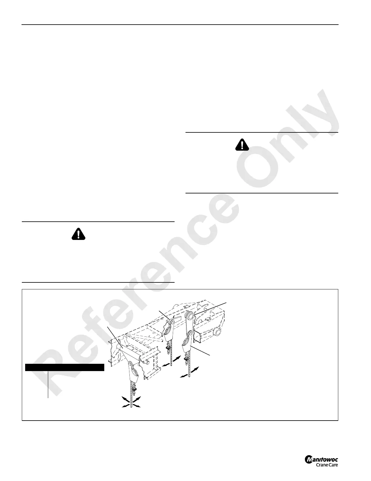
Dead-End
Socket and
Wedge (typical)
Dead-end anchor link (1) and lug (2)
located in or behind lower boom point
provides movement in two directions only.
Forward and back for liftcrane operation
3
1
2
Universal anchor joint (3) located some distance behind lower
boom point, provides movement in four directions. Forward, back
and sideways for magnet, clamshell, grapple, liftcrane and other
operations requiring a 2-part load line (duty-cycle work).
FIGURE 4-52
Item Description
1 Anchor Link
(lower boom point)
2 Anchor Lug
3 Universal Anchor Joint

 Loading...


