Grove Published 07-06-2017, Control # 406-03 6-13
CD5520/YB5520 OPERATOR MANUAL MAINTENANCE
size of the sheave groove. Rough edges, narrow or worn
grooves will cause damage to the wire rope. Replace
any worn or damaged sheaves.
NOTE: As a sheave wears, the groove for the wire rope
becomes smaller. The tracks on the sheave are
caused by the wire rope. Yet, the wire rope will
continue to engage these tracks, for example like a
chain engages a sprocket. As the wire rope turns
and twists on the sheave, the wire rope will move
out of the worn track. This will cause increased
wear on the wire rope.
Grease Fittings
Lubricate all points indicated under the heading Lubrication
Points, page 6-6.
Internal Cable Sheave Lubrication
The lubrication points on the sheaves are not equipped with
grease fittings (zerks) and will require a grease gun adapter
to accomplish the task.
Special Tools:
Nozzle or needle grease gun fitting:
• 6.35 mm (0.25 inch) diameter nozzle grease gun tip
(Grove P/N 955045). Contact Manitowoc Crane Care to
obtain this tip.
• Observation through the sheave case for the extend
sheaves and the hoist mount for retract sheaves.
NOTE: To determine the amount of grease required,
visually inspect the sheaves. From the front of the
boom, look back through the sheave case at the
extend sheaves. From the back of the boom, look
up through the hoist mount at the retract sheaves.
A small amount of grease extrusion around the pin
is adequate.
The extend sheaves are located on the boom tip end of the
extend cylinder, and the retract sheaves are located on the
inside rear of the 2
nd
section. Lubrication is as follows:
1. Extend boom until grease access hole becomes visible
on side of 2
nd
section.
2. Check alignment between the 2
nd
section access hole
and the 3
rd
section access holes. When these holes
become aligned, the end of the extend cable sheave pin
is visible and accessible for lubrication.
3. This boom position also aligns the access holes at the
rear of the 1
st
section for lubrication of the retract
sheaves.
Inner Boom Pad Lubrication
1. With the boom fully retracted, apply grease to the wear
pads on the top of second boom section with a small
paint brush or a grease gun.
2. Extend boom to position the wear pad access holes
directly above the wear pads on the third boom section,
apply grease to the pads using the brush or gun.
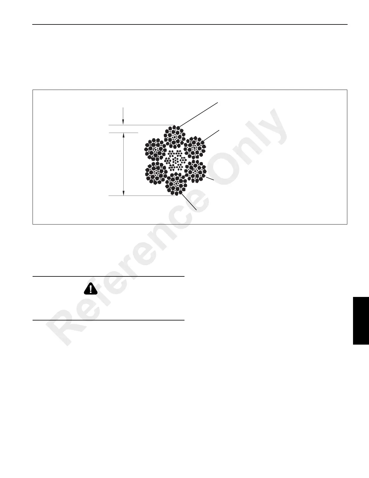
FIGURE 6-23
a0590
Wear greater than 1/3 diameter of
outside individual wires
Reduction from normal diameter of 14
mm (9/16”) of more than 0.8 mm (1/32”)
More than 1 broken wire at a dead-end
connection
6 broken wires in any one lay or 3 broken
wires in one strand in any lay
Kinking, crushing, or distortion of rope
structure
Evidence of heat damage from any
cause
DANGER
Do not, under any circumstances, work at an elevated
height without using proper fall protection as required by
local, state or federal regulations
Reference Only
 Loading...


