OPERATING CONTROLS AND PROCEDURES CD5520/YB5520 OPERATOR MANUAL
3-20 Published 07-06-2017, Control # 406-03
NOTE: The outriggers can not be extended or retracted
when they are in the lowered position. Attempting
to do this will cause damage to the outriggers.
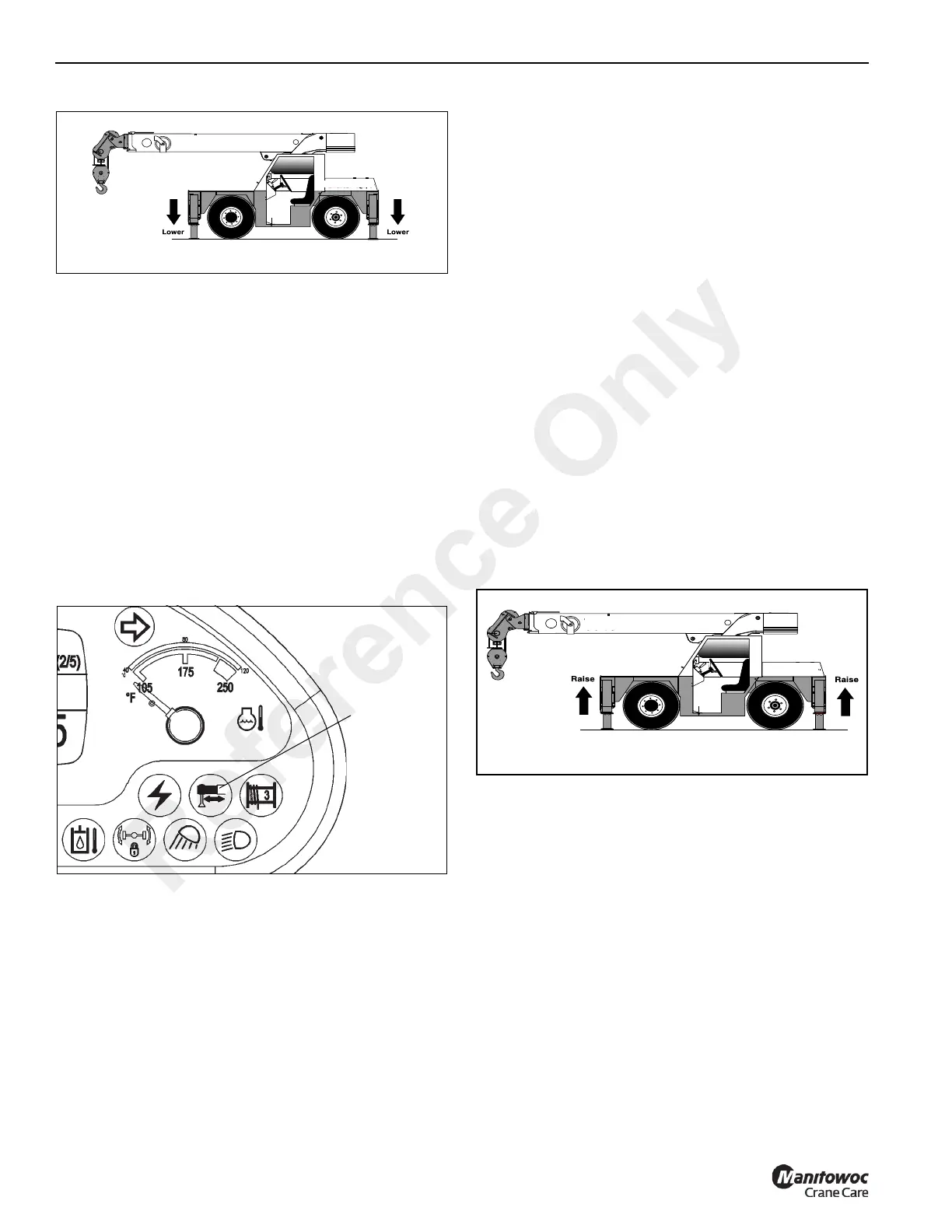
Outrigger Monitoring System (OMS)
(Optional—Standard in North America)
The Outrigger Monitoring System (OMS) aids the operator
by using an indicator (1, Figure 3-28) on the control panel
that lights when all outriggers are fully deployed. The OMS
uses four proximity sensors, one per outrigger beam, to
identify when an outrigger beam is fully extended.
Set up of the outriggers is the same for cranes equipped with
OMS; refer to Operating the Outrigger Controls, page 3-18.
The OMS indicator only indicates the fully extended position
of the outrigger beam and should not be used to deploy the
beam.
Outriggers fully retracted or outriggers fully extended are the
only outrigger positions documented on the Load Charts.
Each proximity switch senses the presence of it’s respective
outrigger beam until the beam reaches it’s fully extended
position.
Proximity switch outputs are wired in series such that when
all outrigger beams are fully extended, each proximity switch
will no longer sense presence of its outrigger beam, the
output contact will then close illuminating the green indicator
on the control panel signaling all outriggers are fully
extended and lifts can be made per “outriggers fully
extended” Load Chart.
Any outrigger beam not fully extended or functional failure of
any proximity switch will cause the indicator to not illuminate,
indicating outrigger beams are not fully extended and lifts
can only be made per the “outriggers retracted” or “on
rubber” Load Charts.
Outrigger beam position monitor is not interfaced with the
rated capacity limiter system (if equipped), the crane
operator is responsible for selecting the correct load chart.
Raising the Jacks
1. Place the Outrigger/Jack selector switches (1,
Figure 3-26) in the jack position—push the bottom of the
switch.
2. Run the engine at idle speed (accelerator pedal
released).
3. Push the bottom of the Extend/Retract Switch (2).
4. Press the accelerator pedal to increase the engine
speed, which will accelerate the upward movement of
the jacks (Figure 3-29). Release the accelerator pedal
and the switch when the jacks are fully retracted.
Retracting the Outriggers
1. Place the Outrigger/Jack selector switches (1,
Figure 3-26) in the outrigger position—push the top of
the switch.
2. Run the engine at idle speed (accelerator pedal
released).
3. Push the bottom of the Extend/Retract Switch (2).
4. Press the accelerator pedal to increase the engine
speed, which will accelerate the inward movement of the
outriggers (Figure 3-30). Release the accelerator pedal
and the switch when the outriggers are fully retracted.
Reference Only
 Loading...


