Grove Published 07-06-2017, Control # 406-03 3-9
CD5520/YB5520 OPERATOR MANUAL OPERATING CONTROLS AND PROCEDURES
Air Conditioning/Heater Controls
The Fan Switch (1) (Figure 3-7) is a four-position switch
which controls the speed of the fan.
The A/C Thermostat Control (2) is used to regulate the
temperature of the air that is delivered.
The Heater Thermostat Control (3) is used to regulate the
temperature of heated air that is delivered.
The air vents (4) are used to direct the air.
The air filter (5) can be removed and cleaned. Refer to
Heater/Air Conditioner Filter, page 6-14.
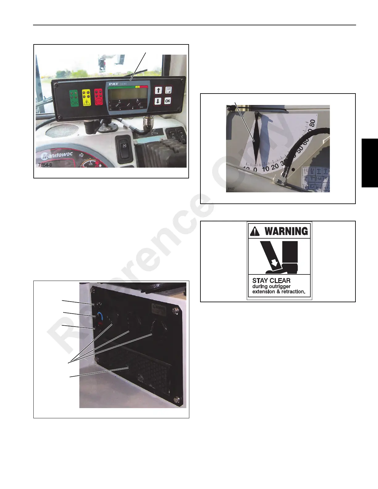
Boom Angle Indicator
The boom angle indicator (Figure 3-8) is a plumb arrow and
a decal with angular graduations from 0° to 80°. One is
located on both sides of the boom and is visible from the
operator’s cab in most boom positions. Use the indicator to
determine the boom angle when reading the capacity chart.
Outrigger Controls
DO NOT allow any persons to stand near extending or
lowering outriggers. Foot crushing could occur.
NOTE: For maximum lift and stability, fully extend and
lower the outriggers. Be sure the crane is level
before lifting a load. The bubble indicator (1,
Figure 3-9) located next to the seat is to be used to
determine when the crane is level. The bubble
must be in the center of the indicator circle. Use the
outriggers to level the crane. If this is not possible,
reposition the crane until the bubble is centered.
If it is suspected that the bubble level indicator is out of
adjustment, verify and adjust the bubble level using the
procedures under Bubble Level Adjustment, page 3-19.
FIGURE 3-8
Boom Angle Indicator
Reference Only
 Loading...


