Grove Published 07-06-2017, Control # 406-03 5-3
CD5520/YB5520 OPERATOR MANUAL ATTACHMENTS
Changing the Boom Head Position (No
Boom Extension)
1. Lower and retract the boom.
2. Lower the block or ball to the ground to take weight off of
the wire rope and boom head.
3. Remove the retaining clip from the rope retention pin,
remove the rope retention pin from the top of the boom
head (Figure 5-6).
4. Remove the lynch pin from the pivot lock pin
(Figure 5-3).
5. Remove the pivot lock pin (Figure 5-4).
6. Position the pin hole in the boom head to align up with
hole or the desired angle. Insert the pivot lock pin
(Figure 5-6) through the holes and install the lynch pin.
7. .
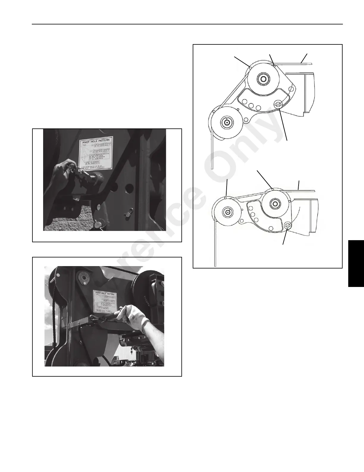
8. When offsetting boom head (Figure 5-5) to +40° run
rope above retention pin 1 to position 2 and run rope
between pin 2 and sheave wheel.
9. When offsetting boom head (Figure 5-5) to +80° run
rope above retention pin 1 to position 2 and run rope
between pin 2 and sheave wheel.
10. After installing the rope retention pin and retaining clip
into the boom head (Figure 5-5). Check that the wire
rope is not contacting retention pin at the top of the
boom head.
NOTE: It may be necessary to remove and stow the
retention pin for later application.
11. Using the hoist control, raise the block or hook ball off of
the ground. Check that the wire rope is engaged in all
the sheaves in the boom, hoist block and hoist drum.
FIGURE 5-5
Position 1
8815-1
8815-2
Pivot Lock Pin
Position 2
Position 1
Position 2
+80° Offset
+40° Offset
Wire Rope
Wire Rope
Pivot Lock Pin
Reference Only
 Loading...


