Grove Published 07-06-2017, Control # 406-03 4-1
CD5520/YB5520 OPERATOR MANUAL CAPACITY CHART
SECTION 4
CAPACITY CHART
SECTION CONTENTS
Using the Capacity Chart. . . . . . . . . . . . . . . . . . . . 4-1
Operating Boom Radius . . . . . . . . . . . . . . . . . . . . 4-1
Locating the Lift Capacity . . . . . . . . . . . . . . . . . . . 4-1
Things to Observe When Using the Capacity
Chart . . . . . . . . . . . . . . . . . . . . . . . . . . . . . . . . . . . 4-1
Lifting with the Boom Extension Installed . . . . . . . 4-2
Pick and Carry Ranges . . . . . . . . . . . . . . . . . . . . . 4-2
USING THE CAPACITY CHART
The capacity chart for this crane is located on the inside of
the operator’s cab to the right of the seat. The chart provides
maximum loads that can be safely lifted and give conditions
under which these maximum lifts can be made.
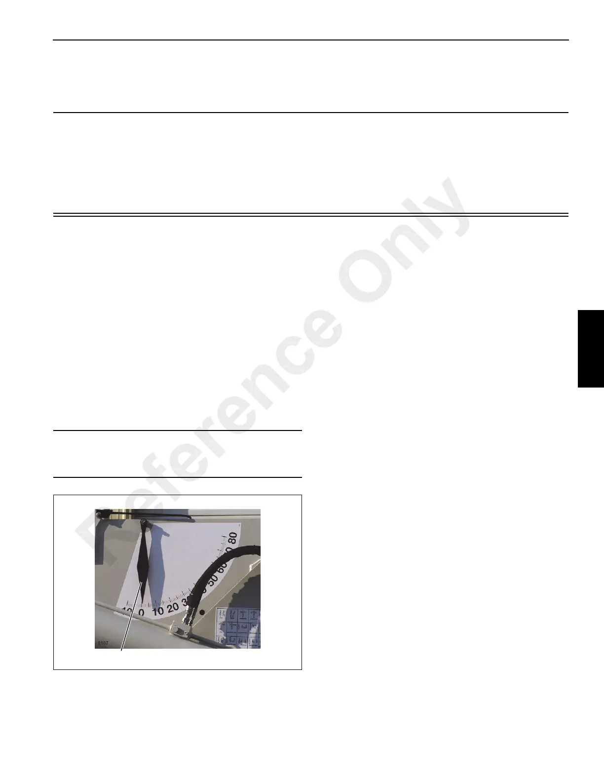
Operating Boom Radius
Located on both sides of the boom is an indicator that gives
the angle at which the boom is positioned (Figure 4-1). The
angle at which the boom is positioned and the length at
which the boom is extended determines the lifting radius of
the boom. For example, if the boom is at a 70° angle and is
extended to 13.25 m (43.5 ft) the lifting radius is 3.66 m
(12 ft). See capacity chart.
Locating the Lift Capacity
Locate on the Capacity Chart the Main Boom Load Ratings.
Find the 10 foot radius in the chart. Always use the next
highest radius if the radius measured is not on the chart.
Read across the line to determine what can be lifted at that
radius, either with the outriggers extended and down,
retracted and down or on rubber.
DO NOT lift more than what the capacity chart states.
Things to Observe When Using the Capacity
Chart
1. The rated loads are the maximum lift capacities as
determined by operating radius, boom length and boom
angle. The operating distance from a projection of the
axis of rotation to the supporting surface, before loading,
to the center of the vertical hoist line or tackle load
applied.
2. The rated loads shown in the Capacity Chart on
Outriggers do not exceed 85% of actual tipping. The
rated loads shown on rubber do not exceed 75% of
actual tipping. These ratings are based on freely
suspended loads with the crane leveled, standing on a
firm, uniform supporting surface. Practical working loads
depend on supporting surface, operating radius and
other factors affecting stability. Hazardous surroundings,
weather conditions, experience of personnel and proper
training must be taken into account by the operator.
3. The weights of all load handling devices such as hooks,
hookblocks, slings, boom extension, etc., except the
hoist rope, shall be considered as part of the load. See
paragraph 1. The weights for these items is stated on the
capacity chart.
4. Rating on outriggers are for either outriggers fully
extended and down or fully retracted and down.
5. Ratings on rubber depend on tire capacity, condition of
the tires and proper inflation pressure of 827 kPa (120
psi). Loads on rubber may be transported at a maximum
CAUTION
To determine the exact lifting radius, use a tape measure
and measure from the center of rotation of the load line.
FIGURE 4-1
Boom Angle Indicator
Reference Only
 Loading...


