WARNING: TO AVOID INJURY FROM AN ACCIDENTAL START, MAKE SURE THE
SWITCH IS IN THE "OFF" POSITION AND THE PLUG IS NOT CONNECTED TO THE
POWER SOURCE OUTLET.
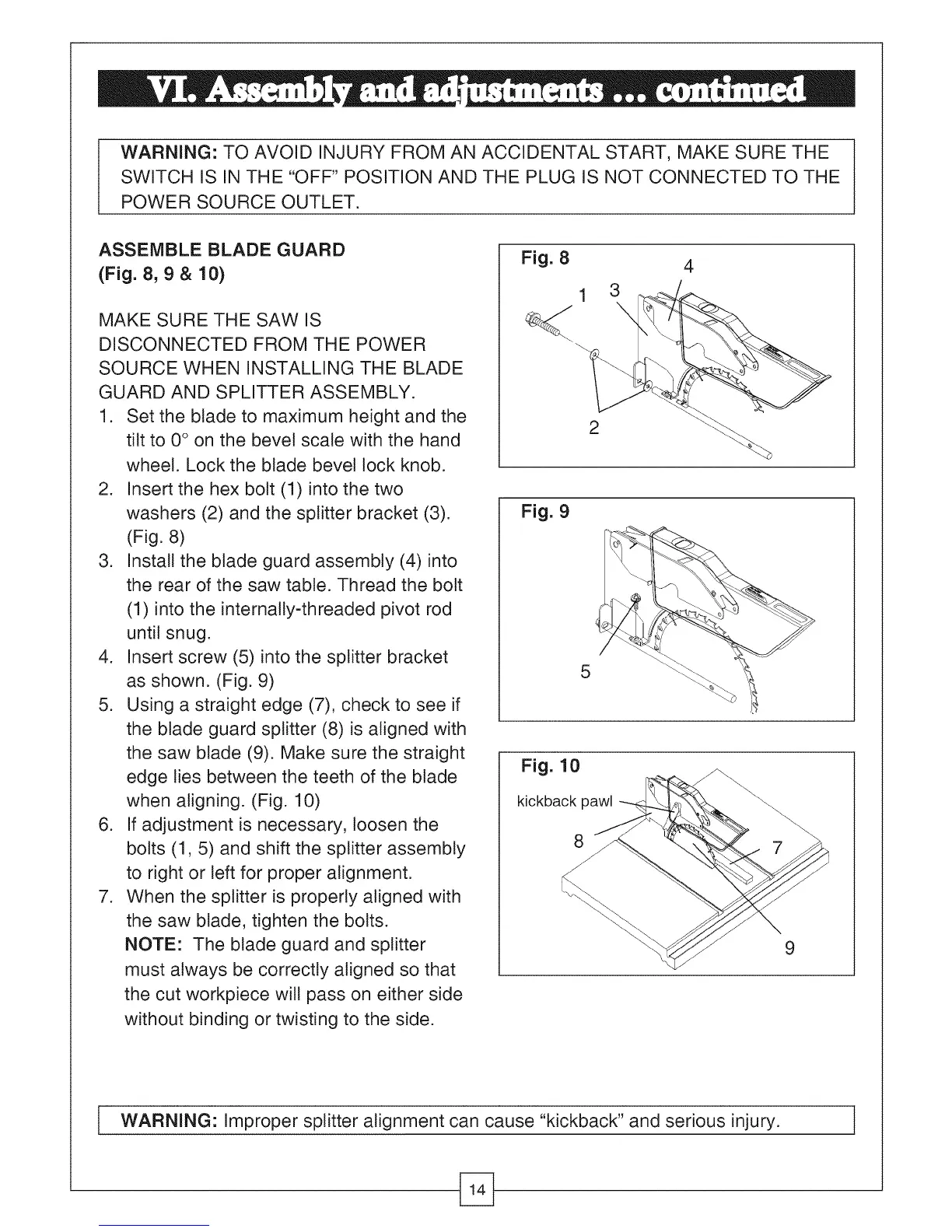
ASSEMBLE BLADE GUARD
(Fig. 8, 9 & 10)
MAKE SURE THE SAW IS
DISCONNECTED FROM THE POWER
SOURCE WHEN INSTALLING THE BLADE
GUARD AND SPLITTER ASSEMBLY.
1. Set the blade to maximum height and the
tilt to 0° on the bevel scale with the hand
wheel. Lock the blade bevel lock knob.
2. Insert the hex bolt (1) into the two
washers (2) and the splitter bracket (3).
(Fig. 8)
3. Install the blade guard assembly (4) into
the rear of the saw table. Thread the bolt
(1) into the internaNy-threaded pivot rod
until snug.
4. Insert screw (5) into the splitter bracket
as shown. (Fig. 9)
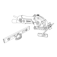
5. Using a straight edge (7), check to see if
the blade guard splitter (8) is aligned with
the saw blade (9). Make sure the straight
edge ties between the teeth of the blade
when aligning. (Fig. 10)
6. If adjustment is necessary, loosen the
bolts (1, 5) and shift the splitter assembly
to right or left for proper alignment.
7. When the splitter is properly aligned with
the saw blade, tighten the bolts.
NOTE: The blade guard and splitter
must always be correctly aligned so that
the cut workpiece will pass on either side
without binding or twisting to the side.
Fig. 8
2
4
Fig. 9
5
Fig. 10
kickback pawl
8
9
i WARNING: Improper splitter alignment can cause "kickback" and serious injury. I
 Loading...