Configure the Active Trim system with the major trim profile that is most appropriate for an individual boat and power package
combination under normal operating conditions.
Each major profile curve shown in the preceding example represents the default, middle setting (adjustable trim profile 3) of a
broader range of adjustable trim profiles. Each major trim profile has a range of five user adjustable trim profiles, to allow the
operator to fine tune the trim curve during boat operation, to compensate for differences in environmental conditions or boat
loading.
The upper limit of a selected major trim profile represents the user adjustable trim profile 5. The lower limit represents the user
adjustable trim profile 1.
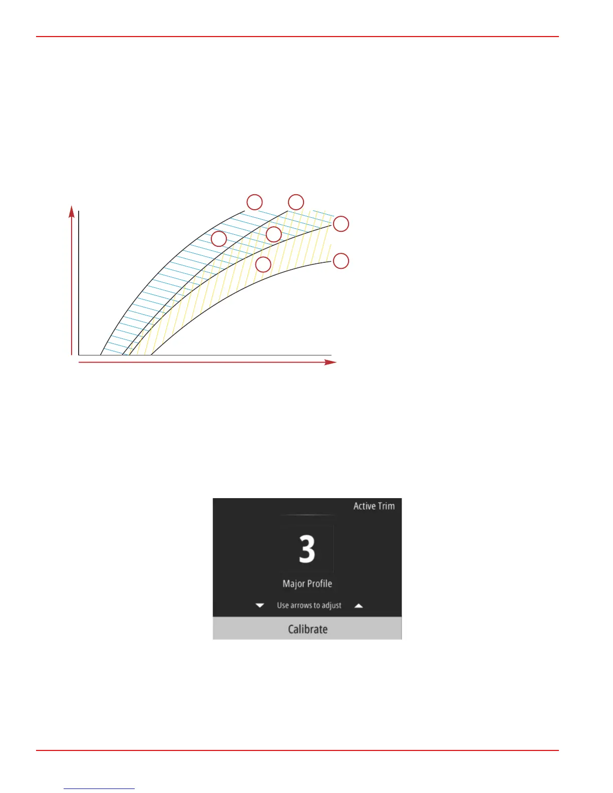
The ranges of the five major trim profiles overlap one another. Placing the trim curve ranges for major profiles 4 and 3 (from the
first graph) onto a single graph shows a substantial overlap. The upper limit for major profile 3 is higher than the lower limit for
major profile 4, yielding a portion of the trim curve ranges that are shared by both profiles. In practice, this means that slight
variations in the conditions at which the system is configured will not translate to large variations in system performance.
a - Upper limit of major profile 4
b - Lower limit of major profile 4
c - This area (c) plus (g) equals the full range of
major profile 4
d - Upper limit of major profile 3
e - Lower limit of major profile 3
f - This area (f) plus (g) equals the full range of
major profile 3
g - Range overlap of major profiles 4 and 3
Setup and Configuration
IMPORTANT: Always configure Active Trim with a major profile that will allow the operator to select an adjustable profile with
additional trim in; avoid selecting a major profile that results in normal operation in adjustable trim profile 1. This will ensure that
the operator can always bring the bow down to correct porpoising without having to manually trim the engine or drive.
The VesselView will search the network for the Vessel Control Module. If the Vessel Control Module software is not up‑to‑date,
or if it cannot be found on the network, the Active Trim setup will not allow the operator to continue.
Highlight the Calibrate option and press the Enter button. Follow the on‑screen directions for each step in the calibration
process. Highlight the Next option following the completion of each step to continue onto the next step. When all steps have
been completed, press the Enter button to save the calibration procedure.
Section 3 - Main Menu Selections
Page 28 90-8M0124182 eng DECEMBER 2017
 Loading...