© 2009 MIMAKI ENGINEERING CO.,LTD.
7.1.2 P.1
1
2
3
4
5
6
7
8
R.1.2
Maintenance Manual > Troubleshooting > Details on Errors and Malfunctions > List of Error Messages
Model CJV30/TPC Issued 2008.08.04 Revised 2009.06.30 F/W ver. 1.20 Remark
1.2
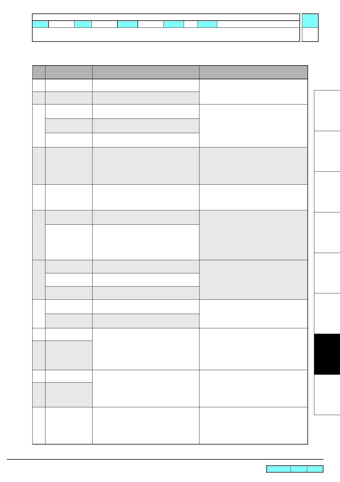
7.1.2 List of Error Messages
List of error messages (1/6)
Error
No.
Indication on LCD Cause Remedy
01
ERROR 01
MAIN ROM
An error occurs on the control PCB (ROM) Turn off the main power, and turn it on a little later.
If the error occurs again, carry out the followings.
1. Replace the main PCB assy. (See 3.4.1)02
ERROR 02
MAIN RAM
An error occurs on the control PCB (RAM)
03
ERROR 03
POWER +5V
An error occurs on the control PCB
(Power voltage +5V)
Turn off the main power, and turn it on a little later.
If the error occurs again, carry out the followings.
1. Replace the power supply PCB assy.
(See 6.5.1)
2. Replace the main PCB assy. (See 3.4.1)
ERROR 03
POWER +24V
An error occurs on the control PCB
(Power voltage +24V)
ERROR 03
POWER +42V
An error occurs on the control PCB
(Power voltage +42V)
04
ERROR 04
F-ROM
An error occurs on the control PCB
(Parameter ROM)
Turn off the main power, and turn it on a little later.
If the error occurs again, carry out the followings.
1. After uploading parameters, initialize all
parameters.
If the state is not restored, replace the main
PCB assy with a new one. (See 3.4.1)
06
ERROR 06
SD-RAM
An error occurs on the control PCB
(SDRAM)
Turn off the main power, and turn it on a little later.
If the error occurs again, carry out the followings.
1. Replace the main PCB assy. (See 3.4.1)
2. Replace the PRAM PCB assy. (See 6.5.3)
07
ERROR 07
HEAD (----)
An error was detected in the head connection.
(Abnormal temperature was detected.)
Turn off the main power, and turn it on a little later.
If the error occurs again, carry out the followings.
Refer to Electrical Troubleshooting ( See 7.2.3 ),
and replace the following parts if it has damaged.
1. Replace the head FFC and the HDC FFC cable.
2. Replace the head.
3. Replace the ink slider PCB assy. (See 6.5.9)
4. Replace the main PCB assy. (See 3.4.1)
ERROR 07
VOLTAGE (----)
An error was detected in the head connection.
(Abnormal voltage was detected.)
08
ERROR 08
LinearENCODER:SENSOR
An error occurred in detection by the linear
encoder. (Counting impossible)
Turn off the main power, and turn it on a little later.
If the error occurs again, carry out the followings.
1. Check of the mounting location for the linear
encoder scale and encoder PCB assy.
2. Replace the encoder PCB assy. (See 6.5.12)
ERROR 08
LinearENCODER:DIR.
An error occurred in detection by the linear
encoder. (Wrong orientation)
ERROR 08
LinearENCODER:COUNT
An error occurred in detection by the linear
encoder. (Read-out count error)
09
ERROR 09
FPGA ERROR
An error occurs on the control PCB
(FPGA PDC)
Turn off the main power, and turn it on a little later.
If the error occurs again, carry out the followings.
1. Replace the main PCB assy. (See 3.4.1)
ERROR 09
HDC ERROR (----)
An error occurs on the control PCB
(FPGA HDC)
10
ERROR 10
COMMAND ERROR
Other data than commands is received. 1. Change over the setting of [COMMON
SETTING] -> [RECEIVED DATA], depending
on the application being used.
2. Clear the data of uncompleted printing.
3. Check the USB cable.
(specifications, cable length, etc.)
4. Replace the main PCB assy. (See 3.4.1)
10C
ERROR 10-C
COMMAND
11
ERROR 11
PARAMETER ERROR
Parameter out of the numeral value range is
received.
Turn off the main power, and turn it on a little later.
If the error occurs again, carry out the followings.
1. Clear the data of uncompleted printing.
2. Check the USB cable.
(specifications, cable length, etc.)
3. Replace the main PCB assy. (See 3.4.1)
11C
ERROR 11-C
PARAMETER
12
ERROR 12
MAINTENANCE COMMAND
Other data than commands is received. Turn off the main power, and turn it on a little later.
If the error occurs again, carry out the followings.
1. Clear the data of uncompleted printing.
2. Check the USB cable.
(specifications, cable length, etc.)
Replace the main PCB assy. (
See 3.4.1
)
 Loading...


